Antenna impedance matching is an important part of any M2M design.
 The input impedance of an antenna needs to be close to the impedance of the radio module. If not then the signal will be reflected back to the radio module. The signal will not be radiated by the antenna. Matching circuits often contains several discrete inductors and capacitors. Even transmission lines can be used to convert the impedance between radio module and antenna.
Matching 50 Ohm impedance
Radio modules (e.g. GSM, HSPA, LTA, Bluetooth, WIFI or GPS) mostly come with a balanced output of 50 Ohm. The impedance of the selected chip antenna or PCB antenna can differ. Often the center frequency or impedance of the antenna jumps a little bit by thickness of PCB or distance to housing or thickness of the housing. All this can be adjusted by matching circuit. Be aware, that the matching circuit will add a loss or will reduce the bandwidth of the selected antenna. The better option is to tune the antenna itself by changing the antenna structure. By using chip antennas out of the shelf you can´t touch the structure. Nevertheless the gap between antenna and ground plane can be used for matching as well. In an ideal world the matching circuit will adjust the output impedance of the radio module to the antenna input impedance. This will end in higher TX power output of the antenna and the optimise RX sensitivity as well.
Balun between radio module and antenna
Radio modules (e.g. GSM, HSPA, LTA, Bluetooth, WIFI or GPS) often come with balun inside. The matching network for designs on chip level acts as the balun transforming the balanced output of the integrated circuit to the unbalanced antenna. Using of radio modules with internal balun force you to select monopole antennas. In some cases balanced output to dipole antennas gives you a benefit, because e.g. a dipole offers a higher antenna gain.
DC blocking
Inside of the balun is often a capacitor. The capacitor blocks the DC voltage from antenna. By GPS modules with active GPS antennas this is inverse. You need the DC voltage at the antenna. Some GPS modules have a DC switch inside, some other shows a DC coupling outside of the GPS module. Just follow the specification of the reference design of the manufacturer.
Harmonic suppression
By chip designs the balun rejects harmonics and out of band emissions. The maximum band emissions are specified e.g. at FCC or R&TEE.
Examples for antenna matching circuits
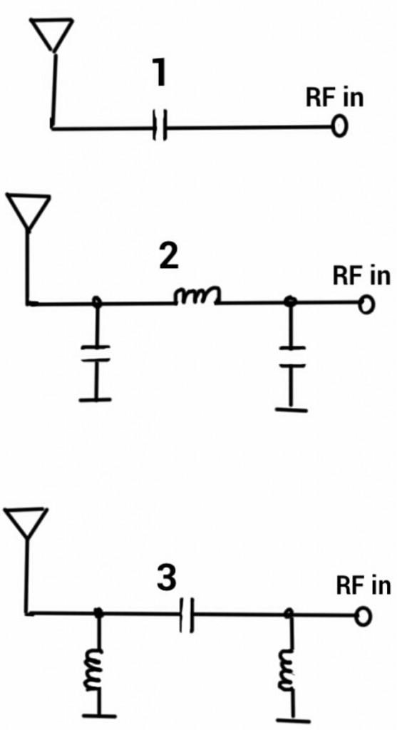
In first step you follow the specification of the supplier of your embedded antenna. If if it not clear then just replace the capacitor in row to a zero Ohm resistor. Worst case the antenna will be mismatched, but will radiate something. For your first steps and tests this is fair enough. Be aware that a big reflected wave can puzzle your radio modules or will generate emissions on your PCB. The final matching circuit cut be just one capacitor or inductor in row (picture 1). You also could end with a Pi circuit (picture 2 and 3). Take care on enough place for components close to the antenna and select capacitors and inductors with small footprint, because smaller footprints will help with less parasitic effects. Each capacitor contains an inductive part and each inductor has a capacitive part as well. Never change the manufacturer of the components you selected during the antenna matching circuit. Take care that the Epsilon R of your FR4 is always the same in each production lot. Best is not the change the supplier of the manufacturer of the PCBs as well. Be aware that impedance testing of your PCB makes the production more expensive and to not save the money for impedance testing of your PCBs.
If you are still not sure how to design the antenna matching circuits just ask for advice by a third party with skills in radio technology and using a network analyzer. Plan one to three working days for optimization the antenna matching. The antenna matching has to be done with final enclosure, because the Epsilon R of your plastic and the thickness of the plastic will effect to the antenna as well.
-
Nothing will interfere your embedded antenna?
-
Why the embedded chip or patch antennas are resonant on the wrong – to high – frequency?
-
How will the ground plane effect your embedded antenna?
-
Which radio approvals has your M2M device to pass?
-
How to connect your embedded antenna with your wireless module?
-
How to design an antenna matching circuit?
-
How to switch between an internal and external cellular or GNSS antenna cheap?
-
Which GPS antenna shall be used for a tracking device?
-
Which embedded antenna to select for a Bluetooth / GNSS application?
-
Dos and don’ts during embedded antenna design in
-
Examples for good and bad M2M designs with embedded antennas
- Q&A: Design in of embedded antennas
please tell me how we calculate the PI network components value
Hi Dhaval, it is explained in my IoT M2M Cookbook:
http://www.gsm-modem.de/M2M/m2m_iot_cookbook/
See also here:
http://www.gsm-modem.de/M2M/m2m-componets/gps-antenna-selection-for-gsm-gps-tracker/