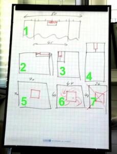
The sketch about GPS antennas was made during a training
1. GPS chip antenna as PIFA
One option are GPS PIFAs. Such PIF antennas are looking for 70 to 80 mm long PCBs. 35 to 40 mm left and 35 to 40 mm right is fine. The shorter the PCB length, the worst the antenna efficiency will be. With 22.5 mm left and 22.5 mm right, you still get a nice result. The length in direction X has to be at least 45 mm. In Y direction the size does not matter.
The centre frequency of this PIFA antenna can be tuned with the gap (ground less area) under the antenna plus matching circuit.
2. – 4. GPS chip antennas as monopole antenna
Option 2 and 3 are showing antennas on the corner of the PCB. Just take care on the data sheets of the GPS antennas. The distance to ground plane is maybe different, by several types of antennas. This antenna type can be tuned by making a stubby (small PCB track) on the open end of the antenna and components in the matching circuit.
5. GPS patch antenna on PCB
Most data sheets name a 70 x 70 mm or 35 x 35 mm ground plane. If you change the size of the ground plane, then the centre frequency will shift. If you put an enclosure on top of the antenna, then the centre frequency will shift again. If you change the thickness of the plastic or the type of the plastic or the distance to the plastic – every change will interfere with the antenna.
5.1 The way out of the GPS patch antenna jungle
Just ask for an evaluation with GPS patch antennas, that comes with centre frequencies of 2 MHz steps. One out of 10 antennas will fit to your application. To limit the tuning trouble you shall select a 25x25x4 mm GPS patch antenna. As bigger the GPS patch antenna is, as bigger the bandwidth of the antenna. As bigger the bandwidth, as less the risk to loose performance. A GPS patch with a size of 18x18x4mm is a good compromise.
6. – 7. GPS patch antenna on non symmetric PCB
GPS patch antennas offers a circular polarisation. The circular polarisation you get by putting the feeding point not in the middle of the GPS patch antennas. The red round shaped lines on the sketch number 6 shows the floating current on your PCB. The current will float circular. Sketch number 6 shows a 40×40 mm PCB. This is OK. At sketch number 7 you see a non symmetric PCB. As soon, the PCB is not quadratic the circular polarisation will be destroyed and the loss will be 3 dB. If your PCB is not quadratic (what is common) then just take care, that the ground plane will be quadratic.
Further GPS antenna types
GPS is on 1575.42 MHz. In this frequency range you can use PCB track antennas inside PCB as well. Such PCB tracks will like the GPS chip antennas have no circular polarisation. Other types are helical antennas on top of the enclosure. Helical antennas you can get unbalanced or balanced with balun. There are helical antennas with SMT mounting as well. Another option are active GPS antenas with short coaxial cables or active GPS antennas to be mounted direct on the PCB.
Conclusion
The selection of the GPS antenna and the tuning plus selection of the GPS module is a difficult task.
If you still not sure which GPS antenna to select and why, then do not hesitate to drop an email to harald.naumann (at) gsm-modem.de
-
Nothing will interfere your embedded antenna?
-
Why the embedded chip or patch antennas are resonant on the wrong – to high – frequency?
-
How will the ground plane effect your embedded antenna?
-
Which radio approvals has your M2M device to pass?
-
How to connect your embedded antenna with your wireless module?
-
How to design an antenna matching circuit?
-
How to switch between an internal and external cellular or GNSS antenna cheap?
-
Which GPS antenna shall be used for a tracking device?
-
Which embedded antenna to select for a Bluetooth / GNSS application?
-
Dos and don’ts during embedded antenna design in
-
Examples for good and bad M2M designs with embedded antennas
- Q&A: Design in of embedded antennas
