Effect of the cut-out zone without copper under the antenna
The device under test is a PCB of size 40 mm x 20 mm, again with a GNSS chip antenna designed for small tracking devices. Small mobile GSM/GPS trackers are common for pets, humans or assets. GNSS chip antennas operate as loop antennas which are magnetic antennas and are usually unaffected by being near to the body. If the device is touched or objects come close to the antenna, the centre frequency will not be de-tuned. In this test, we will have a closer look at the effect of temperature on the resonant frequency of the antenna.
Operation of GPS chip loop antennas
Ceramic loop antenna with two visible pins
You can identify a loop antenna by its two connection pins. One pin will be connected the GPS module and the other will be connected to the ground plane. They always have a cut-out zone without copper on all layers under the antenna. The pin to connect to the GPS module under the antenna will be like the pin in the picture or it will be turned 90 degrees to the other pin connected to ground. Such GPS antennas with their small bandwidth always need tuning. You can use passive components between the GPS module and the antenna to shift the center frequency.
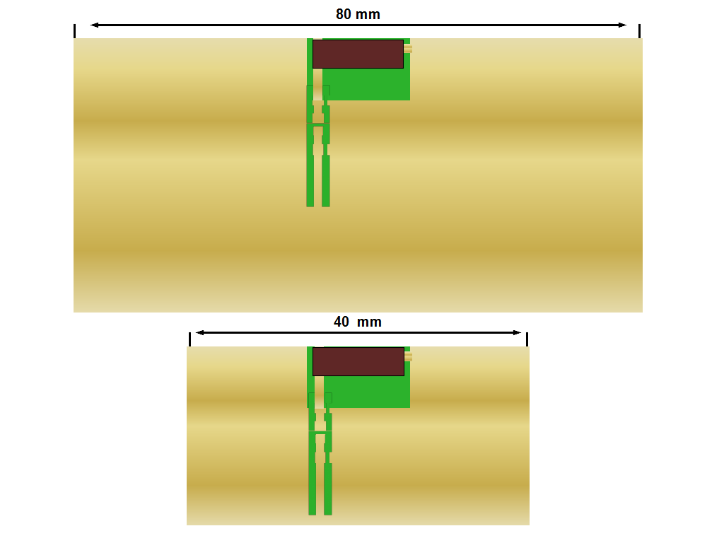
The upper graphic shows a GPS chip loop antenna on an 80 mm and 40 mm long ground plane. Please note that the size of the GPS chip antenna is not to scale. The data sheets often specify the gain and Return Loss for the 80 mm length only. If you use a 40 mm long PCB instead of an 80 mm long PCB you will lose gain and bandwidth. If the bandwidth at 80 mm size is marginal then at 40 the mm size it will be too small. If you move the antenna away from the center of the 80 mm or 40 mm PCB to the left or right you will decrease gain as well.
During this test we will use the 40 mm x 20 mm PCB on the left side of the 3 x 3 PCB array. On a first quick view, all three test PCBs look the same. The cut out zone of the first PCB has a length of 7 mm, the second has a length of 7.25 mm and the third has a length of 7.25 mm.
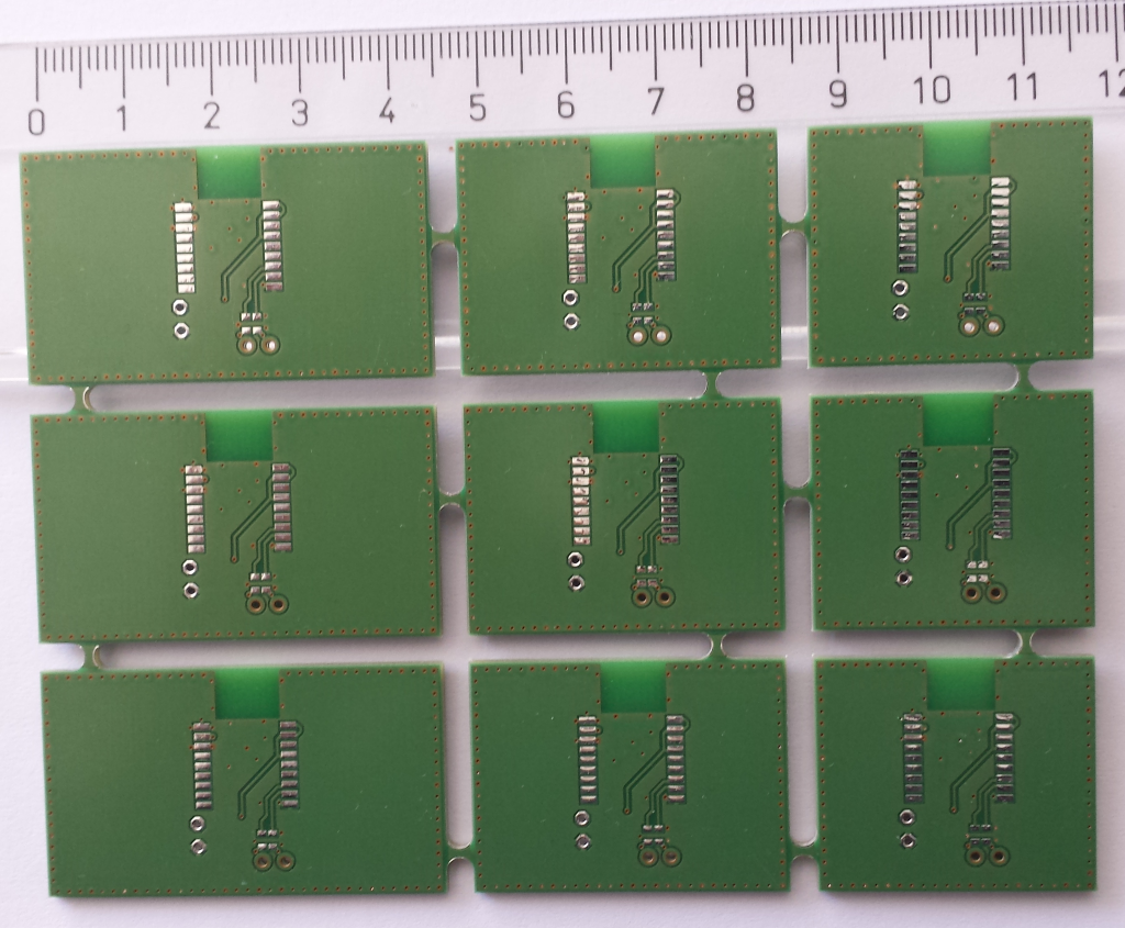
GPS chip loop antenna – test PCB – backside
GPS chip antenna frequency drift
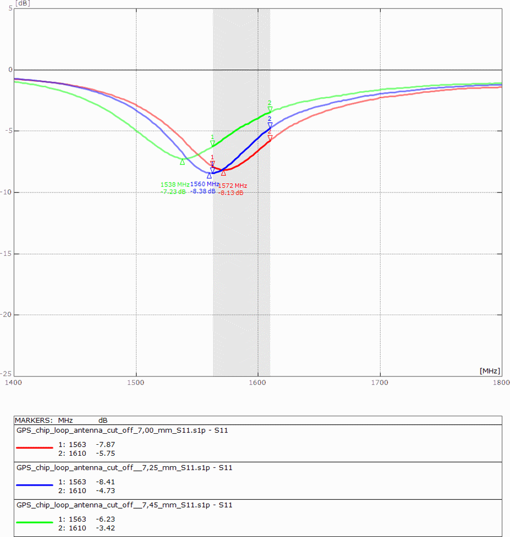
GPS chip loop antenna – drift on cut out zone
The red Return Loss curve shows the GPS chip antenna unmatched on the PCB with a 7 mm long cut out zone. The blue Return Loss curve shows the chip antenna unmatched with a 7.25 mm long cut out zone and the green Return Loss curve is related to a 7.45 mm cut out zone. The delta between 1572 MHz minus 1538 MHz peaks is 34 MHz. This frequency drift is related to the size of the cut out zone of the chip antenna. Because there were no matching components on the PCB we can exclude an effect of the matching circuit on the drift.
GPS chip antenna conclusion
The DUT shows frequency drift of 34 MHz by changing of the cut out zone length from 7 mm to 7.45 mm. The resonance frequency is determined by the GPS chip antenna design, by the cut-out zone and matching components. While matching components have only a small impact on the frequency, they tend to become lossy for a large frequency tune. The cut-out zone has a larger frequency impact. Here the total cut-out perimeter is key. A larger perimeter decreases the frequency, a smaller perimeter increases the frequency. Please note that a frequency shift caused by matching components increases the hand effect (the influence of a body part on performance), while a perimeter trim doesn’t. So make your coarse trim adjustments by changing the cut-out perimeter, and then fine trim with matching components.
GPS chip antenna consulting
The DUT under test has demonstrated that there is a strong requirement for antenna pre-testing and unconventional chip antenna tuning. The method of tuning using the size of the cut out zone is often not listed in the data sheet of the chip antenna.
If you are interested in an antenna pre-testing or antenna consulting for selection then do not hesitate to drop an email to harald.naumann (at) gsm – modem .de
Further GPS chip loop antennas under test
GPS antenna selection for a GSM / GPS tracker – DUT 1
GPS antenna selection for a GSM / GPS tracker – DUT 2
GPS antenna selection for a GSM / GPS tracker – DUT 3
GPS antenna selection for a GSM / GPS tracker – DUT 4
1 Comment
Add a Comment