Are you able to find the mistakes in this GSM module antenna design?
The manufacturer labelled it a GSM adapter for the Arduino platform. We have removed the brand name of the GSM module.
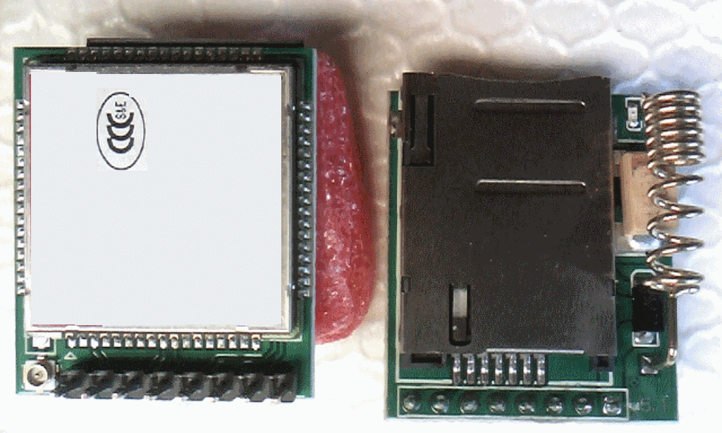
GSM module with helical GSM antenna on PCB
Delivery notes
There were no delivery notes or invoice inside or outside of the package. The customer was really lucky, that the package cleared customs and was delivered.
Arduino header
The Arduino header is missing. There is a board-to-board connector that is not Arguino compatible. The hobbyist or student will therefore have to expend some extra effort to wire the PCB.
Radio certification
The CCC certification marked on the package covers a wide range of products, electrical and non-electrical, which are listed in the CCC category. Unfortunately, CCC is the China Compulsory Certification. In Europe we need CE and in US we need FCC. CCC is not valid in Europe or in the US.
Helical GSM antenna distance
The distance between the antenna and the SIM card connector is so small, that I would expect a power down reset of the SIM card when the TX power of the GSM module reaches 2 Watts. Moreover, the GSM helical antenna lies directly on the (hopefully low value) ESR capacitor. The 2 Watt TX power will go straight onto the DC supply voltage of the module.
Helical GSM antenna consulting
You can expect that the data sheets of the GSM helical antenna manufacturers will show the Return Loss in free space only. To avoid an unpleasant surprise there is a much better approach. The solution is antenna testing by a third party including documentation on Return Loss on a non-matched antenna, simulation of the matching circuit plus matching with passive components and measurement again by a Vector network analyser. In this specific case we disconnected the GSM antenna from the GSM module and fed the GSM antenna via a U.FL connector with a coaxial cable connected to the VNA.
Helical GSM antenna pre-test
- Test with the VNA of the original un-matched antenna on the PCB
- Export to S1P files and export to PNG files
- Simulation of the matching circuit
- Export to S1P files and export to PNG files again
- Test report in PDF format
The pre-test will always contain the test report and the S1P file of the original unmatched PCB. With the pre-test S1P file the customercan simulate matching circuits on their own. Such a pre-test costs only Euro 240. If the selected antenna does not pass the pre-test, then you can stop because you know you will need another antenna for your IoT M2M design. In this GSM antenna test we had to hit the brakes and stop testing.
Grey zone: GSM 850, 900, 1800 plus 1900
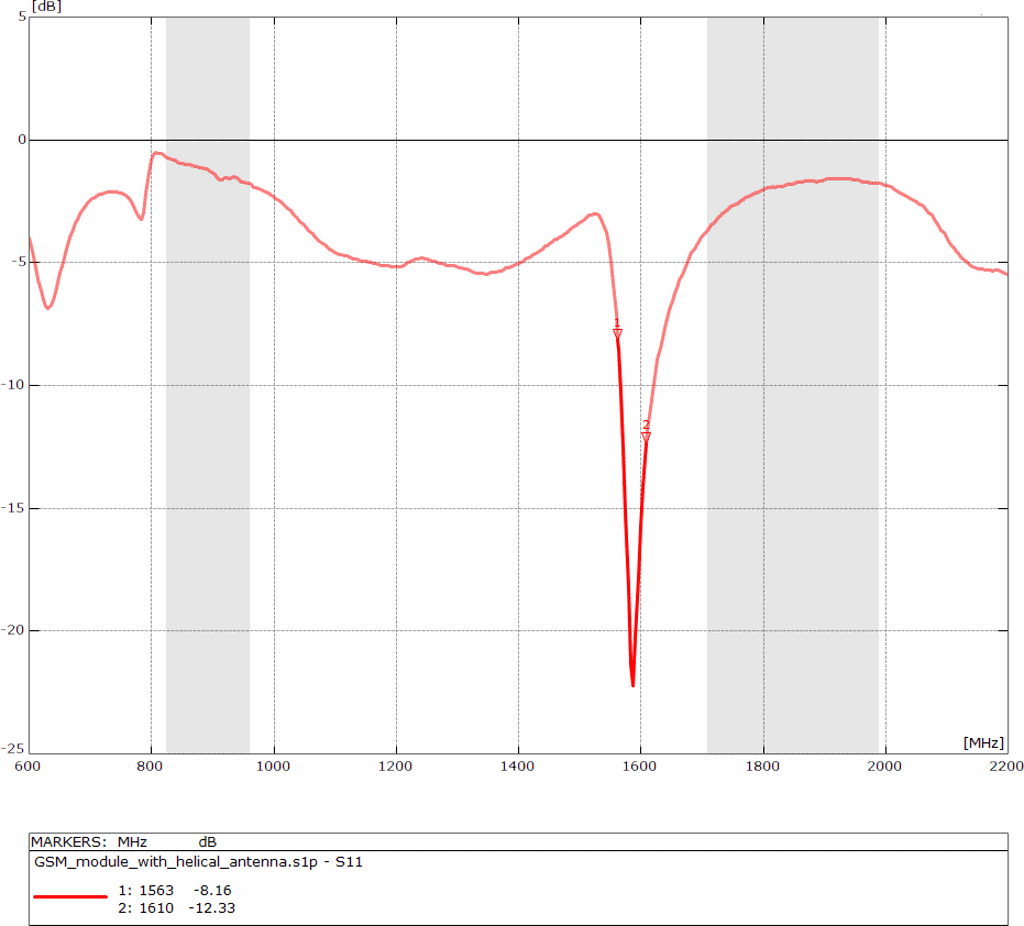
GSM helical antenna – Return Loss – 2
The grey marked zones at the upper pictures mark the GSM frequency bands. The left grey zone marks GSM 850 plus GSM 900 and the right grey zone marks GSM 1800 plus GSM 1900. We expect a Return Loss of at least – 6dB. However, for some reasons the helical antenna is not resonant in the expected frequency range.
Some initial details:
- VSWR: 2 = Return Loss of – 9.5 dB
- VSWR: 3 = Return Loss of – 6 dB
- VSWR: 4 = Return Loss of – 4.4 dB
You can calculate this yourself here http://cgi.www.telestrian.co.uk/cgi-bin/www.telestrian.co.uk/vswr.pl
A VSWR of 3 is the common minimum for embedded antennas.
Grey zone: GPS plus Glonass
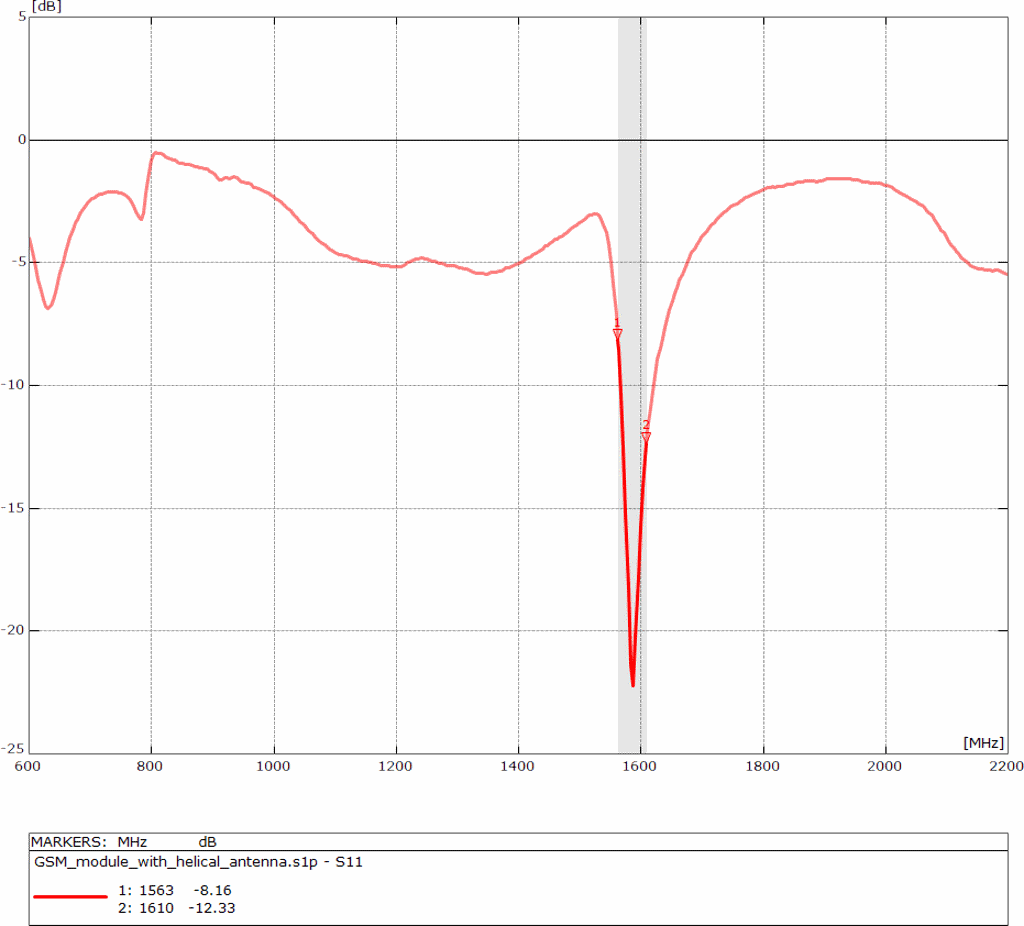
GSM helical antenna – Return Loss – 1
The helical antenna is useless for GSM. For some reasons it is resonant at GNSS (GPS+Glonass).
GSM PCB conclusion
The DUT has failed the test in several areas. A radio module with no CE approval is a non starter. Even with CCC approval the PCB will not pass because it has a completely incorrectly tuned antenna on much too small a ground plane and very close to the SIM holder which will guarantee the generation of spurious emissions.
If you would like to avoid this kind of trouble and if you are interested in an antenna pre-test, antenna test in a real environment or antenna consulting to make a sound selection for your design, then do not hesitate and drop an email to harald.naumann (at) gsm – modem. de