When a rectilinear radio wave hits an edge, it changes its course. This effect is called diffraction. By diffraction, we understand a bending effect during the propagation of electromagnetic and acoustic waves. The diffraction causes a change from the straight-line propagation of the waves and occurs at obstructions, mountains or buildings. A simple, free simulation software considers the diffraction at hills and mountains. The 3-D models of buildings and diffraction at the edges of buildings is unknown to simple software. By the diffraction, at the edges of the mountains, the radio wave experiences an attenuation. This attenuation also depends on the exit angle after diffraction. That the simulation software also takes diffraction and attenuation into account will be shown in the next graphs.
Key data for the simulation:
– Height of gateway antenna = 25 m
– Height of sensor antenna = 1m, 2 m
– Sensor output power: 14 dBm
– Antenna gain sensor: 2.15 dBi
– Sensitivity Gateway: -137 dBm
– Antenna gain gateway: 5.15 dBi
– Sum of all gains and losses: 158.3 dB
Request for a LPWAN in Australia
The example below of an LPWA connection is based on a real request for a radio link in Australia. On the left side of the graph, the 25 m high mast is located on the farmer’s property. The farmer’s field is only 5.6 km away. 5. The distance of 5.6 km is much less than the always mentioned 45 or 50 km range of LPWAN in the license-free band. In this case, the sensor in the field was simulated at 1 m height. As a real example, this was discussed intensively in a forum. The participants of the discussion gave tips and mentioned antennas with high antenna gain that were directed to solve the problem. Directional antennas with high gain are contra-productive in this example. The sensor in the farmer’s field is located behind a hilltop in a countersink. Nobody of the participants asked for the position of the gateway and the sensor. If you really used a directional antenna, it would point with its lob directly towards the hill. A wireless connection from the farm to the field is only possible by the diffraction of the radio wave on the hill near the field. You can only see this if you transfer the locations of the two antennas to simulation software and then simulate the direct connection.
LPWAN Link in Australia with 25 m and 1 m high antenna
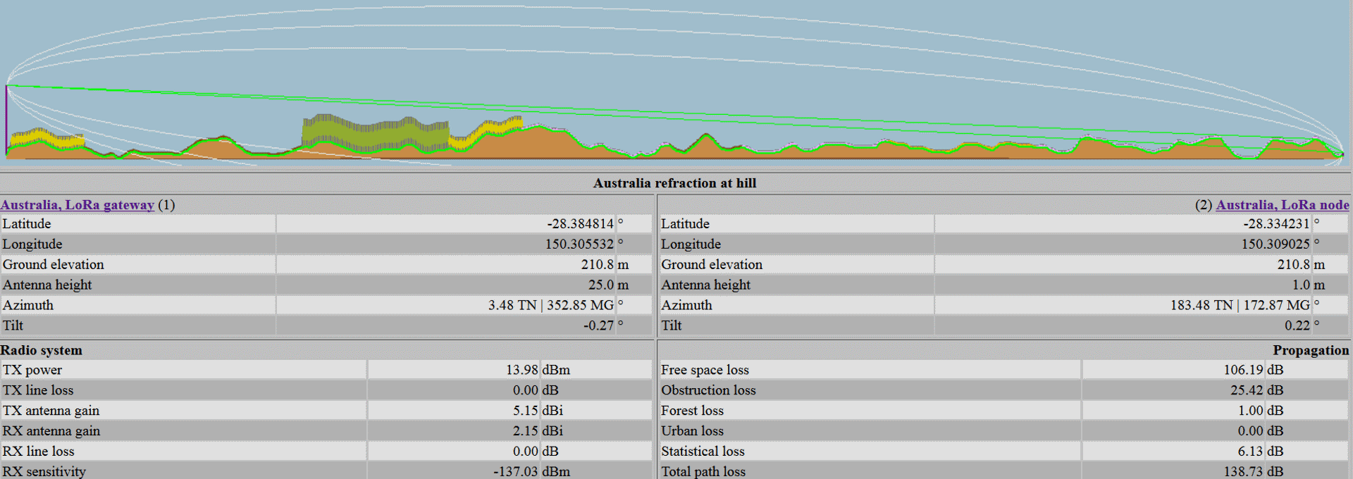
LPWAN with diffraction with 25m and 1 m high antennas
On the left side, you can see the 25 m high antenna of the gateway high above the earth’s surface and obstructions. The yellow-green area next to the antenna shows the vegetation with low trees. This has been taken from a database for vegetation and buildings. The software uses standard heights for certain types of vegetation. The yellow-green area is followed by a light green/dark green area which represents low vegetation. After that follows an area marked in three green levels, which represents high tree cover. Again, standard heights are used. Then follows again a yellow-green area with low trees. Behind this yellow-green area follow further areas with low vegetation. The colour changes several times and also displays green-pink areas. Each colour in the cutaway model represents a known type of vegetation or building. After the high forest followed by the low forest, we find only after low vegetation.
Double line-of-sight in the simulation
The simulation software calculates two line-of-sight. The lower line of sight marked in green hits another hill before the hill in front of the field. This hill blocks a direct radio connection with the sensor in the field. The second line of sight shown in green extends across all fields and hills and is diffracted at the hill directly in front of the sensor and reflected in the direction of the field. This means that a connection with the sensor in the field is only possible indirectly. In addition, the software calculates the diffracted path over the already discussed propagation in the Fresnel zone. The radio energy arrives at the sensor via the propagation in the Fresnel zone as well as the energy through diffraction at the hill. In this example, the software calculates 1 dB loss caused by the forest. This loss occurs because the line-of-sight between the gateway and the diffraction at the hill is very close to the forest. This proximity of the forest cuts the already discussed Fresnel zone. In the simulation, the loss due to buildings is shown as 0 dB. This is realistic because the satellite image of the location tells us that there are no buildings between the antenna on the farm and the sensor. With 138.7 dB simulated path loss, we have almost 20 dB link margin (fade margin 19.55 dB) left. The 20 dB should be sufficient even with field strength variations due to weather changes or rainy weather.
LPWAN Link in Australia with 25 m and 2 m high antenna
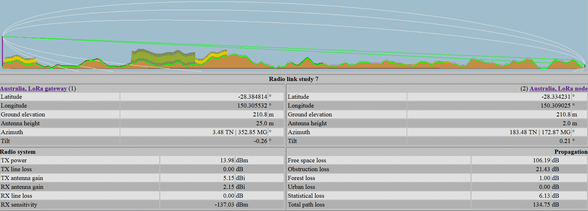
LPWAN with diffraction with 25m and 2 m high antennas
The gateway’s antenna increase from 25 m to 30 m did not significantly improve the link budget. In addition, 5 m more antenna height would require a new antenna mast. Such a new mast would increase the costs for the radio link significantly. For this reason, we have increased the height of the sensor’s antenna from 1 m to 2 m in this simulation. The change of the antenna height from 1 m to 2 m changes the path loss from 138,7 dB to 134,75 dB. The 2 m high antenna on the sensor gives us 4.5 dB more signal. A further optimization at the sensor is not possible. The European radio regulations limit the maximum antenna gain to 14 dBm to 2.15 dBi. We have already used the 2.15 dBi gain in the simulation. The antenna at the gateway has a gain of 5.15 dBi. There it would be possible to use an omnidirectional antenna with a gain of 8.15 dBi. In this case, you have to reduce the radiated power at the gateway. In order to be able to use an antenna with a gain of 5.15 dBi, a reduction from 27 dBm to 24 dBm transmission power would already be necessary. With an antenna gain of 8.15 dBi, the transmission power would have to be reduced from 27 dBm to 21 dBm. In return, the sensitivity of the gateway would improve from -137 dBm to -141 dBm. In the above considerations, the losses in the coaxial plug connections and in the coaxial cables are not taken into account. Quickly, 1 to 3 dB attenuation can be achieved. As mentioned before, we do not consider these attenuations in the simulation.
LPWAN Link in Australia with 25 m and 2 m high antenna in detail
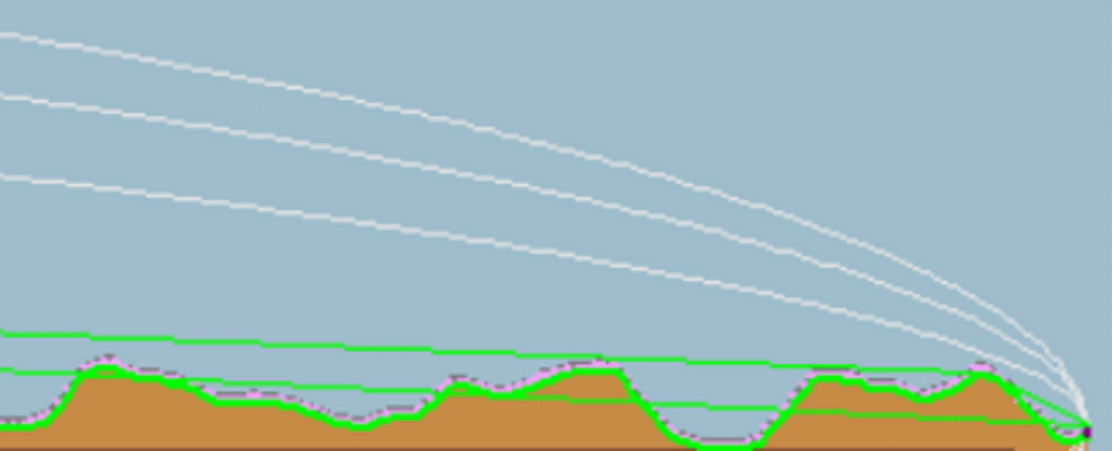
LPWAN with diffraction in detail
If you take a closer look at the radio connection between the farm and the field near the field, you will notice that the radio connection established by a diffracted line-of-sight just goes over two hills in front of the hill of diffraction. If the low vegetation would be replaced by bushes and low trees, the diffracted connection would no longer be possible. Moreover, you can see that the grey line that marks the first Fresnel zone is just above the hill next to the field. A minimally changed tilt of the antenna in the field would also optimize the Fresnel zone.
Summary
This example clearly shows that the simulation software considers the diffraction of radio waves at a top hill. This example also illustrates that the forest near the line of sight generates an attenuation. In addition, it can be seen that the Fresnel zone and curved propagation are also taken into account here.
References
Diffraction https://en.wikipedia.org/wiki/Diffraction
Radio wave diffraction https://www.electronics-notes.com/articles/antennas-propagation/propagation-overview/radio-em-wave-diffraction.php
Anyone who is planning their own private LPWAN is welcome to contact us. We would be happy to explain how to use the software to simulate a wireless network in workshops or online seminars. If you don’t plan your own network and want to use an existing one and want to develop your own PCBs for this purpose, please do not hesitate to contact us. We are happy to share our experience from the numerous LPWAN projects with you. Please send your requests to harald.naumann(at)lte-modem.com