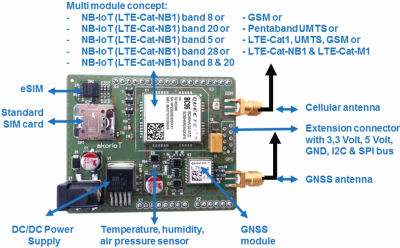
akorIoT Micro Radio adapter with Arduino header and support of NB-IoT, LTE-CAT-M1, EGPRS and GNSS
“akor” is the Proto-Celtic word for “open”. The akorIoT radio adapter with its Arduino R3 header has an open HW and SW concept and supports the multi-mode cellular module B96 as well. Based on that it is the world’s first Arduino shield with the support of both new cellular LPWAN technologies LTE-Cat-NB1 (NB-IoT) and LTE-Cat-M1. On top, there is the support of the common EGPRS. The NB-IoT roll out in Europe has started and in regions without the support of NB-IoT common EGPRS will be used.
The BG96 is a multi-mode module and supports three cellular technologies (LTE Cat-M1, LTE-Cat-NB1 and EGPRS) based on the Qualcomm 9×06 chipset. It supports a maximum data rate of 375kbps in the downlink. It offers an ultra-low power consumption and provides pin-to-pin compatibility with Quectel LTE Cat-1 module EG91, Cat-NB1 (NB-IoT) module BC95, UMTS/HSPA modules UG95/UG96 and GSM/GPRS module M95. With its SMT form factor of 22.5mm × 26.5mm × 2.3mm and high integration level, BG96 enables IoT developers an easy design of low power and inexpensive IoT applications.
Design process of your wireless IoT application
Step 1 – Read the IoT/M2M Cookbook
Cover of the IoT M2M Cookbook
The IoT / M2M Cookbook is intended to help developers of wireless applications to save some time and perhaps to provide some inspiring ideas. It is a book for makers, and the goal of this book is to guide developers from the concept stage of an IoT / M2M device all the way to the final mass-produced product. The book will provide initial details such as how a self-made inverted F cellular antenna works.
Read more: http://www.gsm-modem.de/M2M/m2m_iot_cookbook/
Step 2 – Plug the akorIoT radio adapter on your MCU evaluation kit
The next step will be to plug the akorIoT radio adapter on one of the MCU kits with Arduino header. The STM32 Nucleo evaluation kits give you the freedom to select from 33 different versions:
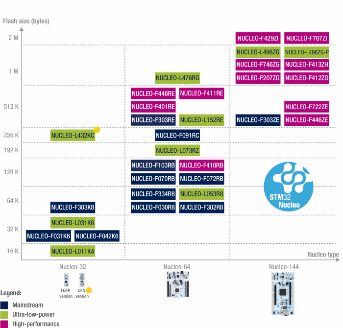
Nucleo MCU evaluation kit with Arduino header – Picture credit: STM
Read more: http://www.st.com/en/evaluation-tools/stm32-mcu-nucleo.html?querycriteria=productId=LN1847
akorIoT radio adapters – 7 different versions
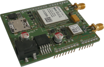
Arduino shield with NB-IoT, LTE-Cat-M1, EGPRS and GPS
akorIoT radio adapters are tested on Arduino UNO and are optimised for STM32 Nucleo, because Nucleo kits offer always more than one UART. One UART will be used for the cellular module and the other for the GPS module. However, the Intel Galileo eval kit offers two UARTs as well. The Raspberry PI will be supported by a common PI to Arduino extension adapter.
Read more: http://iot-university.org
Step 3 – Write your first own code
The Nucleo kits on ARM Cortex Mx are usually enabled for the cloud-based environment ARM mbed C Complier. Based on the open akorIoT philosophy you can easily migrate code developed with the cloud-based mbed C compiler to the ARM supported IDE for free EmBitz. With both IDEs, you will be able to access to the multi-sensor or the GPS module on the akorIoT radio adapter.
Step 4 – Make your first wireless IoT PCB
Parallel to the SW development at step 2 you will start the development of your first own PCBs. The HW development will be done by your team or by the akorIoT team. If your team will develop the PCB, then the akorIoT team will be glad to assist you and to help with design reviews. Moreover, the akorIoT has the skills and the equipment to support you to get a high performed embedded antenna design in.
Step 4.1 Antenna test PCB (option)
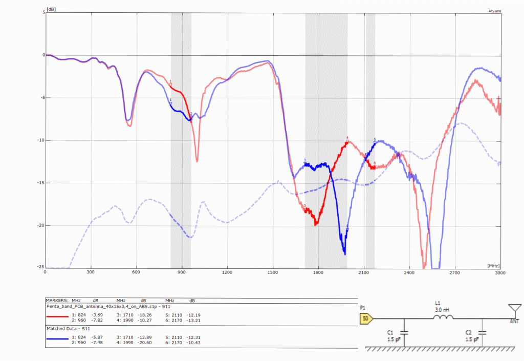
Penta band PCB antenna 40x15x0.4 mm
If you plan a device with embedded antennas then it is highly recommended to develop some “empty” test PCBs with the selected antennas and U.FL plugs. The U.FL plugs will be used to feed the antennas with a Vector Network Analyser. The testing and optimisation can be done by your HW team or by the akorIoT team
Step 5 – Power on of your first PCBs
The code developed at step 2 you will load to your PCB and start with field test. After the field test, you will add the experience to the next version of your PCB, and further field tests will follow.
Step 6 – Mass production

The IoT button / dash button – Fantasy or Business?
After the field test you will make a pre-production followed by mass production. One of the reference list of the akorIoT team you will find a cellular dash button already in mass production. The button has a forecast of 200K+ IoT devices per year. The cellular antenna of the dash button is a customised, reworked version out of the IoT/M2M Cookbook. The bill of material for the embedded antenna is USD. The dash button was optimised on price and performance. The akorIoT team will be happy to guide you from the idea up to mass production as well.
Does this new akorIoT radio adapter gained your interest? Do you have a wireless IoT idea? Do you plan an IoT device with embedded antennas? Do you have an IoT prototype and have a need for optimisation or price? Your one answer is YES. Then do not hesitate to drop an email to harald.naumann (at) gsm-modem.de and to ask for an akorIoT radio adapter or some engineering services to make your IoT idea real.
1 Comment
Add a Comment