The link budget is the total of all losses and gains from the transmission of a radio wave. A wave is amplified or attenuated by the antenna. During the transmission of a signal between transmitter and receiver, data can be lost. The study of losses and gains is therefore important to calculate the reliability and efficiency of a radio link.
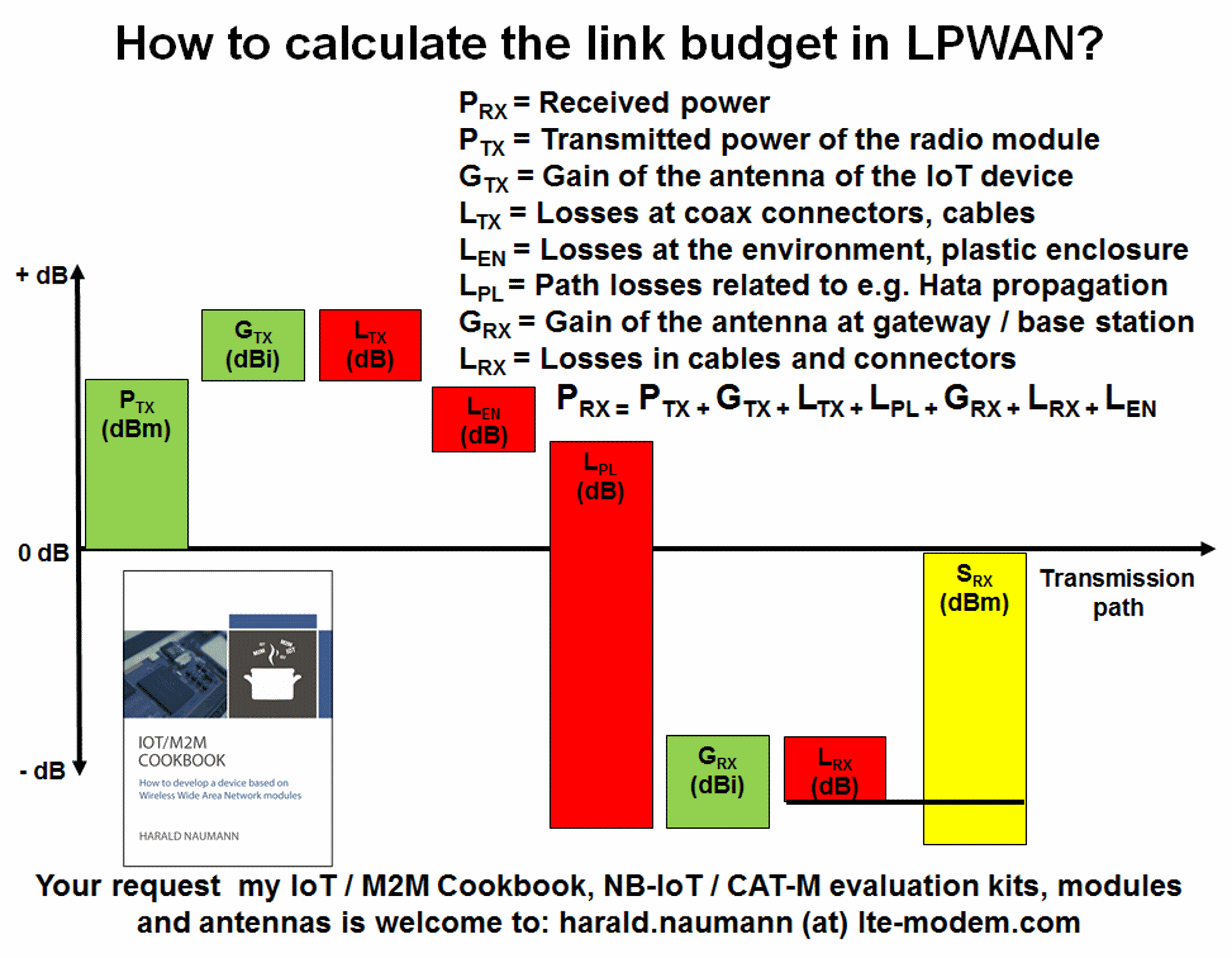
How to calculate the link budget
In order for a signal to be received, the delta of output power minus the total of all losses must be greater than the sensitivity of the receiver. With bidirectional LPWAN radio links the losses between transmitter and receiver apply in both directions. For LPWAN technologies in the unlicensed band, the link budget is usually unbalanced. This means that the transmitter can send to and reach the gateway, but the acknowledgement from the gateway does not reach the transmitter. But the reverse can also be the case. Therefore, the data sheets of the radio modules and the gateways must be carefully inspected. It becomes difficult to do this when manufacturers or network operators do not publish the data. When transmission power and sensitivity are known, only the path losses have to be subtracted from the delta to identify if reception is possible. Some of the losses are under your control: the antenna and the ground plane of the PCB influence the radiated power emitted by the antenna. More than 0 dBd or the corresponding 2.15 dBi cannot be expected with a monopole antenna. In most cases it is less. A part of the radiated energy disappears as path loss in the enclosure of the device. There is usually a matching network between the radio module and the antenna. Energy is also lost in the feed line to the antenna and in the matching network. With a return loss of -6 dB or VSWR of 3, you lose 50 % of the power (3 dB). The rest that remains is not always radiated by the antenna. A part can remain as thermal energy in the antenna or in the enclosure. To detect these losses, the antenna radiation pattern must be measured in at least in three axes.
Link budget and further loses
The energy component which then passes into free space is attenuated over the distance to the second antenna. But the free space attenuation is only half the truth, the nature of the terrain also attenuates the radio wave. A planar water surface has less attenuation than farmland. If bushes, trees and buildings are added it gets even worse. Topography also influences the path losses. At the end of the long path, the radio wave hits a building wall. A cement wall attenuates a 900MHz wave by about 20 dB, another wall in the building quickly by another 8 dB. Losses due to fading only occur in the area near the antenna and are calculated at 8 dB. A loss of 28 dB plus a loss due to free space attenuation must therefore be expected. In 1968, Okumura intensively studied the attenuation of radio waves in cities and developed a theoretical model. This model according to Okumura-Hata runs in the background of simulation software for radio waves. The software adjusts for the topography and the composition of the earth’s surface. All forests with a uniform tree height are included in the calculation. If you want a more accurate approximation, you can change the height of the trees. Buildings and their attenuation are also included using general values. The same applies to water surfaces, cultivated fields and meadows. If required, even the refraction of the radio wave from the top of a mountain or hill can be included. The complex refractions caused by roofs of buildings or the reflection from buildings cannot be included in simple simulation software; this requires 3-D models of the buildings in the cities and high-priced simulation software. The simple software is free of charge and usually sufficient for the planning of private LPWANs. The attenuation caused by refraction on roofs and reflection on house walls can be included in the path loss by anyone in the form of a static value. More about this in a later article.
Enquiries about radio modules, antennas, antenna matching, measurement of the antenna radiation pattern, customer specific antennas or development of complete IoT devices are welcome at harald.naumann(at)lte-modem.com
Literature references:
Okumura, Y.; Ohmori, E.; Kawano, T.; Fukuda, K.: Field strength and its variability in VHF and UHF land-mobile radio service. Review of the Electrical Communication Laboratory, 1968, H. 9-10, p. 825-873.
Hata Model https://en.wikipedia.org/wiki/Hata_model
Link Budget https://en.wikipedia.org/wiki/Link_budget