Ceramic embedded LTE antenna
This LTE antenna with is very detailed documentation is a good example to explain the working of ceramic antennas on a PCB with different size of ground plane.
I. Embedded LTE antenna efficiency
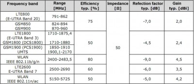
The antenna is resonating in all major LTE, GSM and HSPA bands and on Wi-Fi 2400 MHz and 5 GHz as well. The mentioned parameters are valid on a ground plane with size of 50 mm x 120 mm. The antenna efficiency was measured on a common PCB based on FR4 with a thickness of 1.6 mm.
II. Embedded LTE antenna dimensions
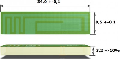
With 34 x 8.5 x 3.2 mm³ the antenna is already very small. The free space area is 50 mm x 20 mm on top of the PCB only.
III. Embedded LTE antenna performance on smaller ground plane
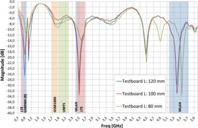
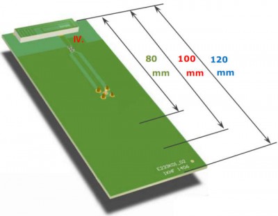
Most embedded antenna documentation does not tell, what will happen by changing of the recommended size of the ground plane. This embedded LTE antenna is telling the true on one few. In the lower bands it will lose performance as usual. The resonate frequency will shift in most of the mentioned frequency bands as well. With a matching circuit it is possible to reduce the detuning by the enclosure. Based on its high bandwidth in the lower bands, the antenna will be perfect for IoT / M2M applications on 2G or 3G modules. As told in the chapter for the self-made GSM Quad band Antenna – as bigger the bandwidth is as lower will be the effort for the tuning.
IV. Cupper nose close to the embedded LTE antenna
The cupper nose is already a part of the LTE antenna. The strip line at the cupper free area is a part of the antenna as well. Do change the width of the strip line, because malfunction will occur.
Summary of embedded LTE antenna
If there is a budget then the antenna structure can be changed. Even the design of an own customised LTE antenna is possible on small to medium quantities. The antenna is always the key to success in any wireless application. They selection of the right antenna in an early stage will decide between success and failure.
If you still not sure which antenna to select and why, then do not hesitate to drop an email to harald.naumann (at) gsm-modem.de
EAD#


How does this perform with 4G
LTE is already 4G. The drawback of LTE is, that the bands are puzzeled worldwide. If I am right, then you are from US. Worst case your LTE operators are on 698 MHz. At this frequency the antenna shows estimated 35%. Maybe it offers more on a bigger ground plane. As lower the lowest frequency ti support as bigger will has to be the size of the PCB.
Anyhow, if you have a budget left, my business partner could place it on a bigger PCB and tell the result.
How about the Antenna clearance area in PWB board for this antenna.
And as in 4G, always MIMO is required to get the throughput, is there the 2nd antenna solution for this concept?
Ma, as told in the text the free space area is 50 mm x 20 mm on top of the PCB only. MIMO you can support only, if you spend a bigger PCB. The PCB has a size of 50x120mm only. This is the typical size of a mobile phone, tracking device or POS system. To support MIMO well, you will need a bigger distance between two antennas. Anyhow, it is up to you to place two of it in 90 degree angle on same PCB or to use an internal and external antenna in parallel.