As the question about the costs and the procedure for the matching of antennas frequently occurs, we have described the process and explained it with some examples of projects. To estimate the costs, the answers to the following questions are necessary.
Standard questions on antenna matching:
- Which radio modules were used?
- How many radio modules / antennas are on the PCB?
- Which type of antennas were used?
- Which radio modules / radio ICs were used?
- Is a battery built into the housing, and what are the dimensions of the battery?
- What are the dimensions of the PCB?
- What are the dimensions of the housing?
- What is the application?
- How many units do you plan to produce per year?
- In which countries / regions should the device be certified?
- Is the PCB prepared with a U.FL socket as described in the IoT / M2M Cookbook?
The akorIoT team expects:
- Two PCBs, fully equipped with the enclosure
- Permission to change the PCBs mechanically for measurement
- Data sheets or hyperlinks to the antennas used
- Manufacturer and type of radio modules
If the PCB has been prepared accordingly, we charge 240 Euro for the matching of a single-band antenna. The matching of multiband antennas costs 240 Euro per band. If possible, frequency bands which are close together are combined and considered as one band. Here are a few examples: NB-IoT antennas for band 8 and band 20 or GNSS antennas for GPS and Glonass are considered as one band. The four different frequency bands or regions of SIGFOX are all in the range from 900 MHz to 1000 MHz and can be combined if necessary. This is similar for LoRa and LoRaWAN. Quadband antennas for GSM 850, GSM 900, GSM 1800 and GSM 1900 are considered as two bands because GSM 850 and GSM 900 overlap like GSM 1800 and GSM 1900. If cellular bands below 800 MHz or above 2000 MHz are added, further costs will be incurred. If the first measurement shows that an antenna for three bands is easy to match, only two bands will be charged for.
We measure and record the actual status (return loss), simulate a matching network, adapt the antenna with 2 to 4 components, specify the components and measure the return loss again. If the simulation shows that antenna matching is impossible, we stop immediately and only calculate the partial step. In addition, devices in series production can also be measured on a test sample basis. Since the PCB material is included in the matching network, it should not be changed. On the other hand, this means that a change in the PCB material requires a review of the matching network.
The preparation of the PCB will be charged on a time and material basis. If no U.FL socket is planned on the PCB, we place a socket manually by hand. It is possible that the board will not be functional after this manual rework. If there is not enough space for a U.FL socket, we need a partially assembled PCBs without radio modules or we desolder the radio modules from the PCB. Instricutions on placing the U.FL socket on the PCB is explained in the IoT / M2M cookbook.
As an option, the antenna can be measured in three axes on the antenna-radiation-pattern. The whole device is then rotated three times in three axes in 10 degree steps on a rotary table with stepper motor by 360 degrees. This costs a sum of 360 euros for three axles. For multi-band antennas the amount of 360 Euro is charged several times. A good return loss is not equivalent to good radiation. akorDolly is a good example of a perfect return loss, but an uneven radiation. The head of akorDolly prevents equal radiation in all directions. The same happens with large batteries in the housing. With akorDolly the sum of the radiation shadows results from the radiation shadow of the head and the radiation shadow of the battery in the housing.
Furthermore, there is the option of accompanying the radio certification. In addition, we offer services around the inspection of the PCBs on the routing of the tracks and the inspection of the schematics at extra cost. If internal development capacities are lacking in your business, the akorIoT team will be happy to take over the task.
Services around the antenna
- Matching of antennas as described above
- Selection of antennas
- Development of customer-specific antennas
- Test setups with empty PCBs with standard antennas and customer-specific antennas in the housing
- Workshops at the customer
- Seminars and training on antenna design, PCB layout and radio certification
- Development of complete devices with internal and external antennas
Examples of antenna matching and antenne designs
The following examples are showing the application, the wireless technology used, the task and the solution.
Radio tag with LoRa – Chip45
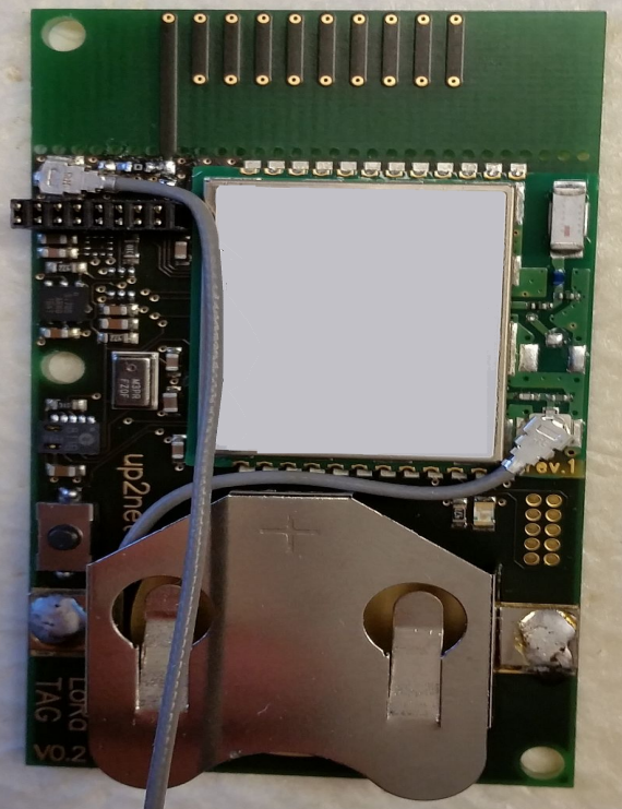
LoRa Tag without enclosure
Chip45’s LoRa tag is a typical contracted development for a matching network with recommendations for improving the antenna during redesign. Since we have the permission of Chip45, we can show the return loss before and after the antenna matching. The complete report can be found here: http://www.gsm-modem.de/M2M/antenna-test/helical-pcb-antenna-lora-tag/
akorDolly – different radio techniques
akorDolly – Virtual sheep to test antennas
At akorDolly we have received a functional device from the series production and work to improve it. We have replaced the expensive ceramic antennas for Globalstar and GNSS with PCB track antennas. The new customer-specific antennas already have 50 Ohm without a matching network. There are no longer any losses in the matching network. In addition, the BOM was reduced by USD 4.
Gillette order button – GSM with preparation for NB-IoT and LTEM – Nexolink
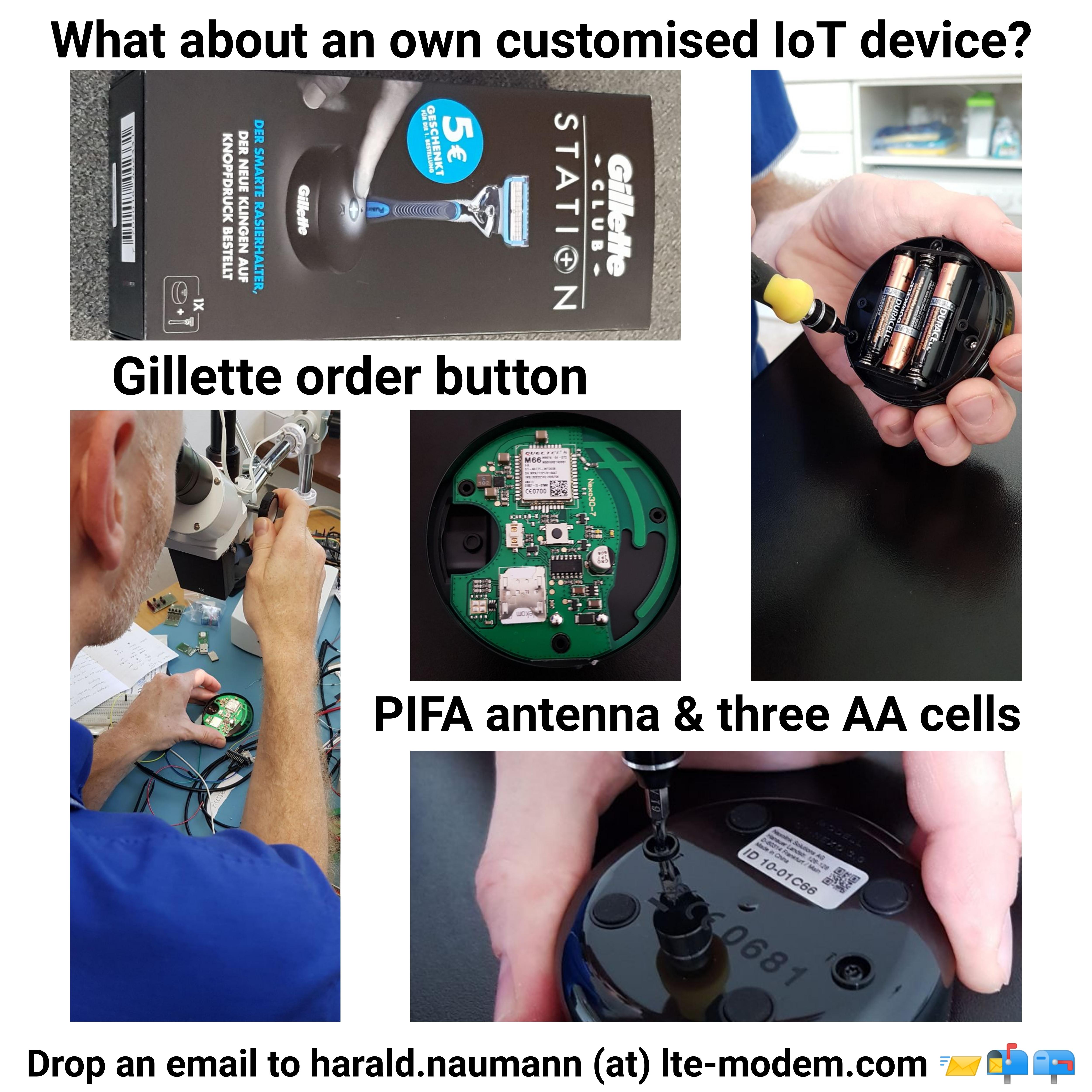 For the order button, the whole device was developed by the akorIoT team. We received a working prototype from Nexolink. The requirement was: function and certification in all European countries. A GSM module was selected and NB-IoT and LTEM prepared for the antenna. The consumer product had the need for a low production price. This was achieved with the rounded PIFA antenna and outperformed the antenna performance of smartphones several times over. We had signal receiving from the second lower parking deck in the underground car park. All smartphones of the customer had no reception there. The whole story to the order button: http://www.gsm-modem.de/M2M/m2m-apps/the-journey-to-develop-the-gillette-order-button/
Bicycle tracker – SIGFOX with preparation for NB-IoT – BFOM
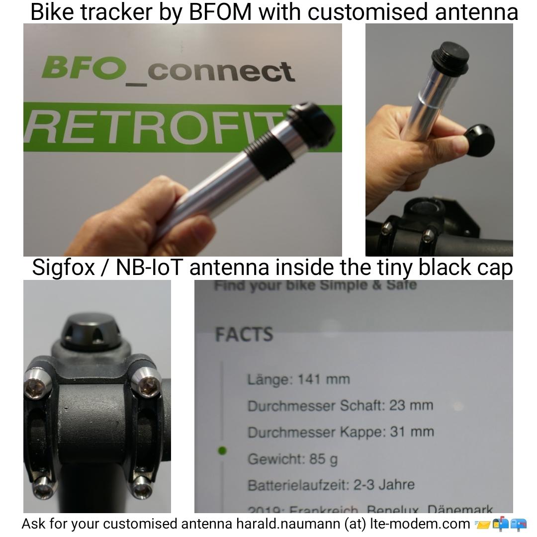
Bike tracker at Eurobike
The task of the BFOM Tracker Retrofit in the fork of the bicycle was to find a solution for the antenna that was as hidden as possible. In the workshop in BFOM’s office, with eight participants, it was discussed how the antenna for trackers should be designed. The bicycle frame constructor, the designer, the product manager and the antenna developer have totally different perspectives. Two worlds came together – Physics met Design. The result is impressive. What you don’t see are the 27 different approaches to the construction of the antenna. If we had started with the 27th antenna, we would have been spared 26 prototypes. Unfortunately, that’s wishful thinking. The smaller the housing or groundplane is, the more test setups have to be made.
AAL system in the wall with akorWALL – GSM and WiFi – Pikkerton
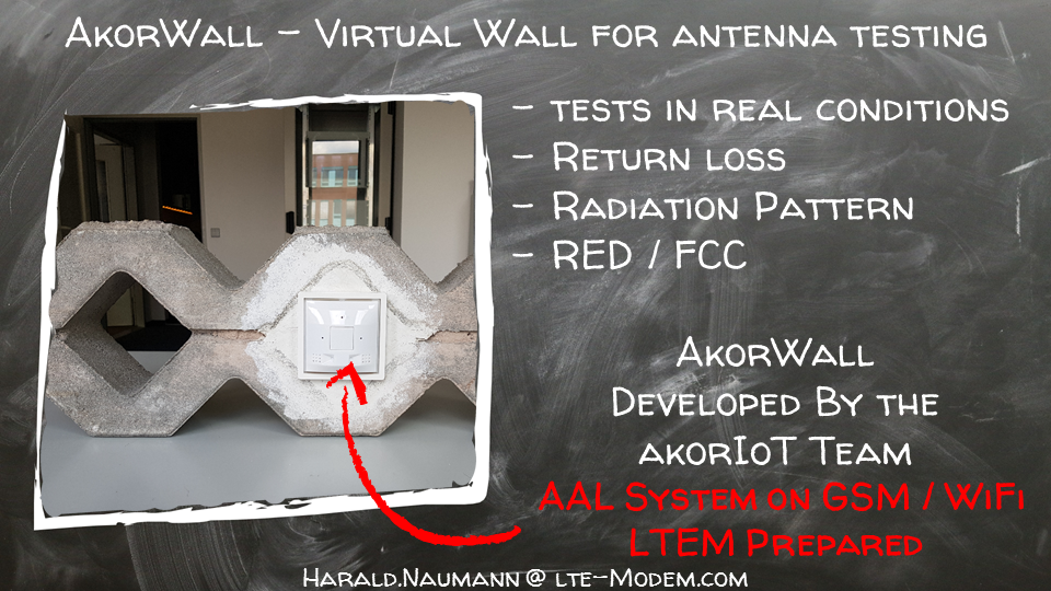
Virtual wall for antenna testing
The ambient assited living system GrannyGuard from Pikkerton was handed over to us as a functional prototype. The task was to integrate a GSM antenna and a WiFi antenna in the flush-mounted switch. The planned chip antennas for GSM and Wifi were quickly discarded and replaced by a customised Flex-PCB antenna. Standard antennas from well-known manufacturers had no function in the arrangement of flush-mounted box and wall. The wall is already part of the antenna system. If the flush-mounted switch is operated without a wall, the antenna no longer works perfectly. Wall, plastic housing, PCB and antenna form a combined antenna system.
Summary antenna matching
The examples above show that some antennas planned by the customers could not be used in the end. Incorrect planning of the antenna leads to unnecessary costs. It is better and cheaper to do a workshop with the BFOM tracker and to discuss the installation space and location of the antenna. Standard antennas are generally documented in free space. The akorDolly and GrannyGuard are good examples of devices that are not in free space. An IoT device that is to be screwed to a metal container must be considered as a whole and requires a customised antenna at the end. Ignoring this leads to a poor return loss. However, a poor return loss leads to higher consumption of energy or often to the emission of harmonics. The harmonics, which are too high, then lead to the rejection of radio certification.
If you are interested in an antenna matching, a customised antenna or a development of an whole IoT device, do not hesitate to contact us. Furthermore, the akorIoT team is happy to hold workshops on the customer’s location for decision making. Feasibility studies, prototypes with function or consulting are also part of the services. For inquiries please contact harald.naumann (at) lte-modem.com