The antenna design in this LoRa-Tag is based on the application note for the Texas Instruments DN038. The customer’s project objective was to match the antenna to the European 868 MHz band without changing the structure.
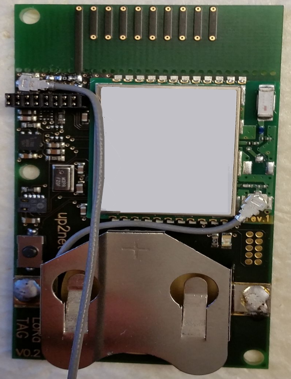
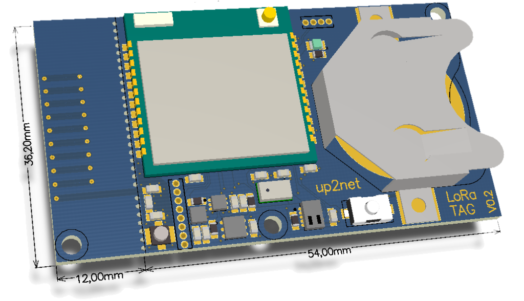
LoRa Tag without enclosure
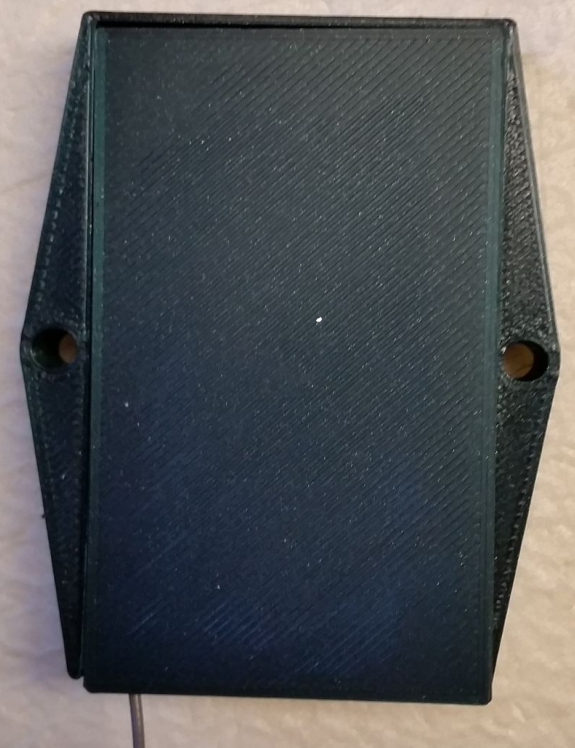
LoRa-Tag with enclosure
Text excerpt from the TI application note
“There are several ways to tune an antenna to achieve better performance. For resonant antennas, the main factor is the length. Ideally, the frequency which gives least reflection should be in the middle of the frequency band of interest. Thus if the resonance frequency is too low, the antenna should be made shorter. If the resonance frequency is too high, the antenna length should be increased. Even if the antenna resonates at the correct frequency it might not be well matched to the correct impedance. Size of ground plane, distance from antenna to ground plane, dimensions of antenna elements, feed point and plastic casing are factors that can affect the impedance.”
This text regarding the DN038 is valid for any antenna structure. Even an SMT mounted chip antenna will change its impedance on a change to the distance to the ground plane. SMT mounted chip antennas have a radiator of set length. If they support multiband for cellular, then most of the time you will have no opportunity to make the radiators longer.
Helical antenna for LoRa-Tag not matched
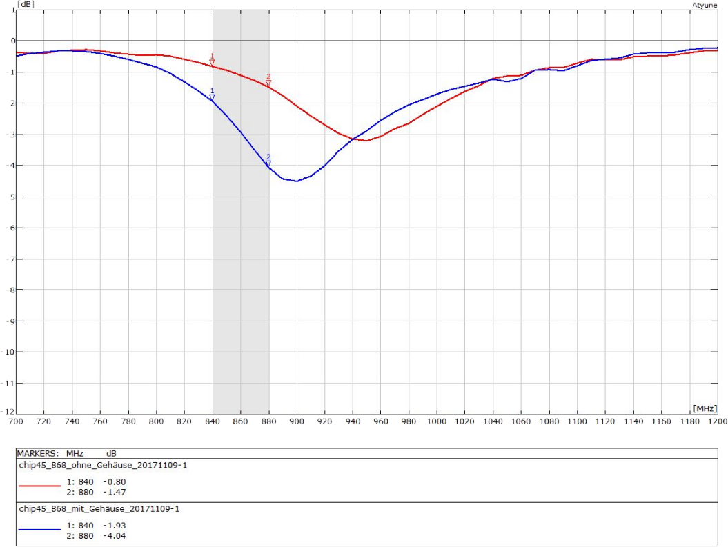
LoRa antenna return loss – with and without enclosure
In this LoRa-Tag project, the length of the helical PCB antenna structure was not changed. As a first step, we always measure the resonance of the antenna with enclosure (blue return loss curve) and without enclosure (red return loss curve). Both resonance frequencies are in the region of 868 MHz. If we put the PCB in an enclosure then the center resonant frequency jumps from 950 MHz to 900 MHz. Such a jump is common. With 900 MHz the center frequency is still too high. The helical PCB antenna is too short. To minimise the design effort we did not expand the PCB track of the antenna and tuned by using a matching circuit only.
Helical antenna for LoRa-Tag tuned and matched
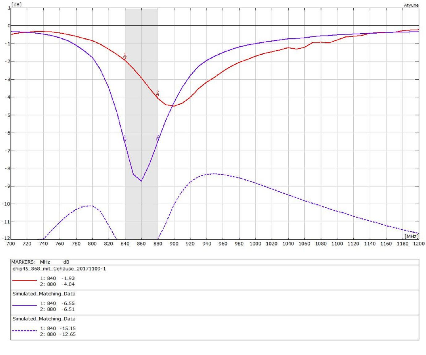
LoRa helical antenna matched
To make the antenna longer you just add an inductor in a row to the antenna. Our free of charge software does the calculation for matching and tuning automatically. We input the center frequency and the bandwidth and pressed the button to start the calculation. For the LoRa-Tag we used a higher bandwidth than necessary because we cannot know where the tag will be mounted. If the end customer screws it on a plastic carrier box, then the center frequency will jump down again. Be aware that screwing onto metal will short the electric field and detune the antenna immediately. For screwing it on a metal chassis, we need another more complex antenna concept.
Recommendations for the antenna at LoRa-Tag
LoRa Tag antenna 3D drawing
For a proof of concept, the selected helical PCB antenna is okay. If the LoRa-Tag moves to mass production, then it makes sense to lengthen the track of the helical PCB antenna. Moreover, it makes sense to stretch the antenna and to use the complete board space. Based on that change the distance to the ground plane of the PCB antennas will be bigger. With greater distance, the impedance of the antenna will increase. According to the TI application note, the impedance is already too low. With an impedance closer to 50 Ohm the loss in the matching circuit will be lower. A lower loss means a better range or a lower power consumption.
The unused board space for the antenna of this LoRa-Tag is quite large. We could consider using an F-antenna. In this case, the antenna structure of the F antenna will be a meander or a helical PCB antenna similar to the basic TI design.
Redesign to SIGFOX or Weightless
SIGFOX and Weightless in Europe are on the same frequency band. The antenna structure could be the same. The bandwidth including the distance between the three LoRaWAN upload channels is 200 KHz x 3 = 600 KHz. For SIGFOX it is 195 KHz and for Weightless it is only 100 KHz. The upload frequencies for LoRaWAN and SIGFOX are given. In case of Weightless, we recommend using the 100 KHz block close to the download frequency and far away from the LTE frequencies at band 8. Remember that the highest LTE frequency for band 20 upload is 862 MHz. An LTE router close to the IoT device in the 868 MHz band could avoid blocking problems because such a router will transmit on 23 dBm. Nevertheless, in summary, the 100 KHz frequency block for upload and the frequencies for download will be much smaller than for LoRaWAN. The smaller the bandwidth is the easier it is to develop an antenna with -10 dB return loss or better at the band edges. The lower the return loss, the less energy will be reflected back to the wireless module.
Any antenna application note with a shape you adjust and implement to your PCB immediately requires a redesign. Your PCB will be a different size and you must understand that the manufacturer’s reference designs are always matched in free space without an enclosure. Nevertheless, your IoT device will of course always have an enclosure.
Has this article piqued your interest? Do you plan your own LPWAN IoT device? Do you plan to deploy IoT devices with embedded antennas? Do you have an IoT prototype and need to optimise the design or minimise the price? If you have answered YES to any one of these questions then please do not hesitate to drop an email to harald.naumann (at) lte-modem.com and to ask for a proposal or some engineering services to make your IoT idea a cost-effective reality.
References:
Application note TI DN038 http://www.ti.com/lit/an/swra416/swra416.pdf
IoT / M2M Cookbook: http://www.gsm-modem.de/M2M/m2m_iot_cookbook/
LTE frequency bands: https://en.wikipedia.org/wiki/LTE_frequency_bands
Interference Measurements in the European 868 MHz ISM Band with Focus on LoRa and Sigfox 868 MHz band https://vbn.aau.dk/files/249716101/ISM_band_interference.pdf
Dear,
Did you use a 1.6mm PCB ?
From the application note, I understood the matching network had to be re-calculate in that case.
thanks !
Houtain, it was a 1.6 mm PCB. The matching has to be calculated on PCB size, PCB thickness, and the plastic enclosure.
Is it possible to find the dxf or the eagle library for that helical antenna ?
The source of the antenna is mentioned in the article.