Low frequencies in the 900 MHz range are a blessing and a curse for LPWAN. The low frequencies spread further in the open field and penetrate the walls of buildings better. But the curse of the low frequencies is the much wider Fresnel zone. To ensure undisturbed transmission, the space between the transmitter and receiver must be free of obstacles of all kinds. In this case, obstacles are not only objects in the direct line of sight between the two antennas, but also objects in a curved curve between the two antennas. Any obstructions lead to reflections and therefore to interference with the direct radio wave. This curved wave propagation follows an imaginary rotational ellipsoid. The area around the direct radio beam and the area around the rotational ellipsoid must be free of obstacles. This area, in the form of a rotational ellipsoid, is called the first Fresnel zone after the French engineer Augustine Jean Fresnel. Fresnel zones can be used to estimate the degree of additional attenuation caused by the obstacles.
The following figures illustrate the Fresnel zone above the earth’s surface. At the edge of the ellipsoid, the detour for the signal diffracted at obstacles is half a wavelength. Inside a Fresnel zone, the path difference, which is the difference between two propagation paths, is less than half a wavelength.
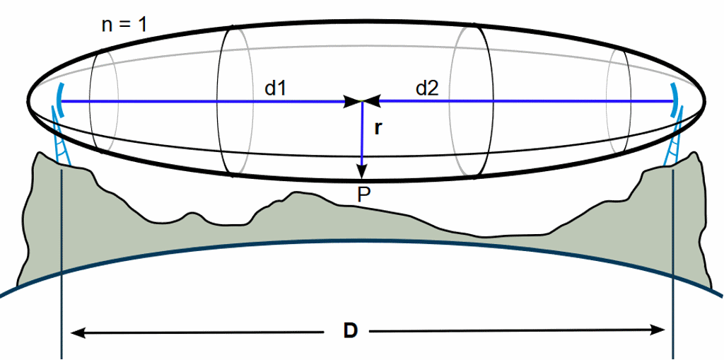
Fresnel zone, source Wikipedia, author: Jcmcclurg, licence CC BY-SA 3.0
In the area of the first Fresnel zone the main part of the energy is transferred. This area should be free of obstacles (e.g. houses, trees, mountains). Since we are in the middle of the North Sea with the simulation, there are no obstacles caused by buildings in the area.
If there are obstacles, the transmission will be attenuated. When the first Fresnel zone is half covered, the additional attenuation at the receiving antenna is 6 dB. The first example illustrates that the 1st Fresnel zone is free of obstacles. Unattenuated radio transmission is therefore possible. This ideal case is then worsened step by step and the result explained. As the sea surface is free of any buildings, one can directly recognize how the simulation software deals with the changed antenna heights.
The distance of 47.7 km between the two antennas resulted from two mouse clicks on Google Maps. The target was a distance of 45 km to 50 km, because this is repeated again and again by the marketing departments of LPWAN. The antenna location “Close to Helgoland” was chosen so that the island of Helgoland is partially covered by radio during further simulations and observations. The antenna “Close to Helgoland” is located west of Helgoland. The site “Far to Helgoland” is further west from Helgoland.
Key data for the simulation:
– Height of gateway antenna = 169 m, 85 m
– height of sensor antenna = 169 m, 85 m, 1m
– Sensor output power: 14 dBm
– Antenna gain sensor: 2.15 dBi
– Sensitivity Gateway: -137 dBm
– Antenna gain gateway: 5.15 dBi
– Sum of all profits and losses (link budget): 158.3 dB
Selected losses in the simulation:
– Margin, sum of the path loss through the first wall and fading: 28 dB
– Link budget minus loss in the wall and fading: 130.3 dB
LPWAN Link in the North Sea with 169 m and 169 m high antenna
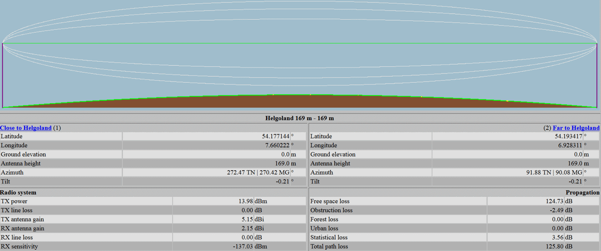
LPWAN Helgoland radio link on 169 m and 169 m mast
lpwan-helgoland-radio-link-vers-LoS-169-169m
The transmission power and of the gateway and also of the node correspond in the simulations to the maximum permitted values in Europe. Important is that the sum of transmission power and sensitivity of the receiver plus antenna gain results in the requested link budget. This is 158 dB in our examples and corresponds to the link budget of LoRaWAN in Europe.
LPWAN Link in the North Sea with 85 m and 85 m high antenna
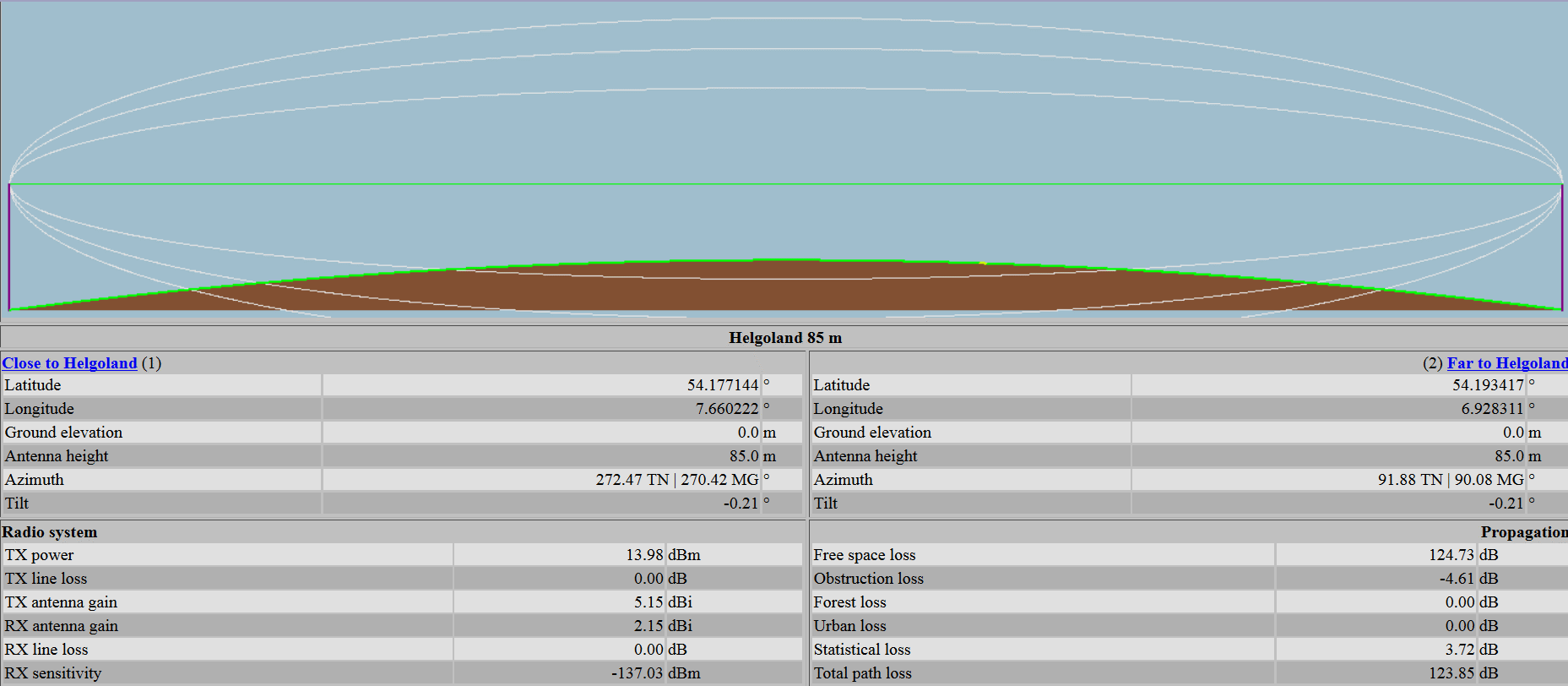
LPWAN Helgoland radio link on 85 m and 85 m mast
As a result of two 85 m high antennas, the first Fresnel zone is just barely touched and therefore only approximately the free space attenuation is displayed. The obstruction loss is -4.61 dB. This means that the software includes a gain of 4.61 dB. The Statisitacl Loss is 3.72 dB. In total, the path loss is close to the free space loss.
LPWAN Link in the North Sea with 169 m and 1 m high antenna
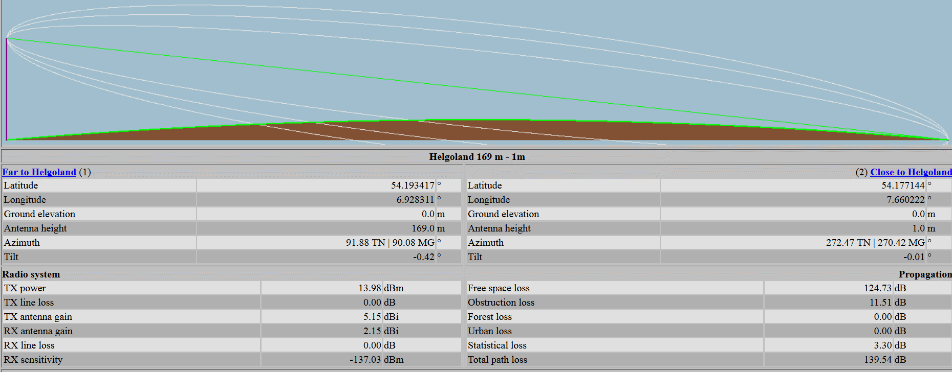
LPWAN Helgoland radio link on 169 m and 1 m mast
In this example with 169 m high antenna and 1 m high antenna there is again a line of sight between the two antennas. The first Fresnel zone and the other Fresnel zones are also completely cut off here. The software calculates approx. 15 dB attenuation even though a line of sight exists.
Summary visual connection and Fresnel zone
A wireless link above the sea surface is certainly the ideal case. In the real world there probably won’t be many LPWAN in the middle of the sea. The simulations above demonstrate, that the software considers the Fresnel zones in the background and shows a attenuation when cutting the Fresnel zone. The attenuation by the land surface of the earth is certainly also considered. To determine this, we would have to compare a radio link above the sea surface with a radio link above an approximately flat land surface.
References
Fresnel zone: https://en.wikipedia.org/wiki/Fresnel_zone
Fresnel zone calculator: https://www.everythingrf.com/rf-calculators/fresnel-zone-calculator
Fresnel zone calculator (1. to 4. zone) https://tomclegg.ca/fresnel
Anyone who is planning their own private LPWAN is welcome to contact us. We would be happy to explain how to use the software to simulate a wireless network in workshops or online seminars. If you don’t plan your own network and want to use an existing one and want to develop your own PCBs for this purpose, please do not hesitate to contact us. We are happy to share our experience from the numerous LPWAN projects with you. Please send your requests to harald.naumann(at)lte-modem.com