Parameters of antennas
In addition to the mechanical dimensions and the type of connection, data sheets for antennas specify various electrical and physical parameters.
1. Antenna gain
The antenna gain is a relative quantity that refers to a reference antenna. The reference value is the receiving field strength of the selected antenna in receiving direction to the receiving field strength of the reference antenna. The reference antenna is either an isotropic antenna or a half-wave dipole. The isotropic antenna is an imaginary antenna which transmits uniformly in all directions (sphere). The gain is given in dBi. The “i” indicates the isotropic antenna as reference.
The isotropic antenna can be compared to an electric light bulb without a screen. It would shine almost uniformly in all directions – it cannot radiate any light in the direction of its socket, where it has a zero point.
The second known reference antenna is the half-wave dipole. In contrast to the isotropic antenna, this can really be constructed. The half-wave dipole has two null points and radiates no energy in these directions. If it is used as a reference, the gain of an antenna is given in dBd. The “d” added to the unit dB indicates the half-wave dipole.
| Antenna type |
Gain [dBi] relative to the isotropic antenna | gain [dBi] related to the half-wave dipole |
| Monopole antenna | 1,6 | -0,6 |
| ?/2 omnidirectional antenna | 3 | 1 |
| Yagi antenne | 5 – 15 | 3 – 12 |
| Parabolic antenna | 15 – 25 | 13 – 23 |
Table 2: Typical values for the antenna gain of the most important antenna types in comparison.
The values in dBi can be directly converted to dBd and vice versa – 0 dBd corresponds to 2.15 dBi. The confusion of dBi and dBd is already the first pitfall when comparing data sheets. If an antenna looks 2 dB better, this may only be due to the comparison with the isotropic antenna (Table 2).
An antenna is a passive component, it cannot amplify. The gain of an antenna is always due to its directivity. The gain of the ?/2 omnidirectional antenna is associated with the small aperture angle of the antenna. With the 5/8 radiator, the gain is even greater and the beam angle is even smaller. The directional effect can be seen most clearly with the Yagi antenna or parabolic antenna. There the energy is directed in one direction and almost nothing is radiated to the rear. The gain, however, will always be indicated in the main beam direction. The parabolic antenna resembles the street lamp with reflector. The light is bundled and directed downwards.
Since in this lecture portable devices or small devices with integrated antennas are considered, the data sheets of the antennas offered always contain values around approx. 0 dBi or 0 dBd.
Antennas for mobile radio (NB-IoT, LTE-M, GSM or LTE) are always designed as antennas with multi-resonance. Good data sheets name the gain in the bands individually and not just the peak value in one of the bands. Even better is a graphical representation of the gain across all bands. A peak with a lot of gain in the middle of a band is of no use, because an IoT device should be able to transmit and receive almost identically in the entire frequency range.
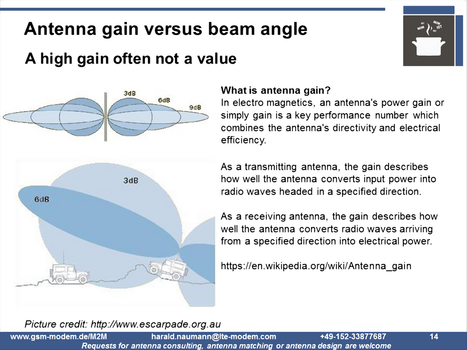
Antenna gain and beam angle
2. Opening angle of the antenna
The beam angle is indicated for ?/2 antennas and other omnidirectional antennas or for directional antennas. It results from the points in the antenna diagram where the gain decreases by 3 dB compared to the maximum in the main beam direction (see diagram with the cars).
With integrated antennas, it is unusual to specify the beam angle. GPS patch antennas with their extreme directivity are an exception. Some antenna manufacturers show the directional diagram in 3D in their data sheets.
A high antenna gain is not always an advantage. For mobile applications in particular, the beam angle of the antenna is relevant (see diagram with cars) for safe operation. Developers must therefore consider both parameters when selecting the right antenna for their application.
Has this article series piqued your interest? Do you plan your own LPWAN IoT device? Do you plan to deploy IoT devices with embedded antennas? Do you have an IoT prototype and need to optimise the design or minimise the price? If you have answered “YES” to any one of these questions then please do not hesitate to drop an email to harald.naumann (at) lte-modem.com and to ask for a proposal or some engineering services to make your IoT idea a cost-effective reality.
Thanks for the article
Kolado, thanks for the feedback. Further free resources on the subject of antennas with texts by me.
1) Linkedin thread, 13800 followers, 11000 contacts in Nov 2023. I write 2 to 3 posts of about 3000 characters per week about antennas, wireless IoT and SIM cards https://www.linkedin.com/in/naumann/
2) Linkedin newsletter: There is a newsletter every 2 to 3 weeks.
https://www.linkedin.com/newsletters/iot-m2m-times-6869017415733280768/
3) Various white papers and studies: https://www.akoriot.com/white-papers/
4) IoT M2M Cookbook. Excerpt here: http://www.gsm-modem.de/M2M/tool/
Have fun reading.
Regards Harald