Transmission line: The PCB track between GSM module and embedded antenna
PCB trace impedance / transmission line calculators
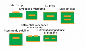
If there is no coaxial cable between your antenna and the GSM module then there is often a PCB track. A coaxial cable has an inner conductor, an isolator and a shielding. GSM modules or other wireless modules like ANT, Bluetooth, WIFI, HSPA, LTE and others offer an impedance of 50 Ohm. Some modules offer a coaxial connector where you can connect a coaxial cable easy. A lot of wireless modules offer just 3 pins. These 3 pins are the 50 Ohm port. In the documentation of the GSM module is explained how to achieve a short proper 50 Ohm track to a coaxial connector. To connect a PCB track antenna or a chip antenna we need a transmission line that offers 50 Ohm impedance as well. The mechanical structure of a transmission line is close to the coaxial cable. You will find a conductor, a shielding and an isolator. The isolator is your PCB material. Often it is FR4. The Epsilon R of FR4 will interfere the 50 Ohm impedance. A common value for Epsilon R of FR4 is 4,2. The Epsilon R of different manufacturers can be different. That means a change of the supplier of the FR4 could force a recalculation of your transmission line. This also means that you can’t make a 1 to 1 copy of the transmission line of the evaluation kit of the wireless module. The common transmission line is called Microstrip line. It is a PCB track on top layer flying over the ground layer. The ground layer can be the layer on the bottom or on an inner layer. Often the GSM module is on the top layer. The PCB track of the Microstrip line will start on the top layer as well. If the PCB track antenna or the GSM chip antenna is on the top layer as well, then it is easy to connect the GSM module with the embedded GSM antenna. If possible it is a straight PCB track from the GSM module to the antenna. If you can’t make a straight track, it is highly recommended not to use an edge of 90 degree. 45 degree twice is already better and the best will be to use a round shape transmission line instead of hard 45 degree edges. With a little luck Microstrip lines with round shapes are already supported by your PCB layout software. If not or if you are not sure how to use PCB layout software it makes sense to hire an external consulter.
PCB trace impedance / transmission line calculators
- PCB Trace Impedance Calculator Online 1
- PCB Trace Impedance Calculator Online 2
- PCB Trace Impedance Calculator Online and download 3
If you have a need for antenna consulting , then just drop an email to harald.naumann (at) gsm-modem.de
-
Nothing will interfere your embedded antenna?
-
Why the embedded chip or patch antennas are resonant on the wrong – to high – frequency?
-
How will the ground plane effect your embedded antenna?
-
Which radio approvals has your M2M device to pass?
-
How to connect your embedded antenna with your wireless module?
-
How to design an antenna matching circuit?
-
How to switch between an internal and external cellular or GNSS antenna cheap?
-
Which GPS antenna shall be used for a tracking device?
-
Which embedded antenna to select for a Bluetooth / GNSS application?
-
Dos and don’ts during embedded antenna design in
-
Examples for good and bad M2M designs with embedded antennas
- Q&A: Design in of embedded antennas
