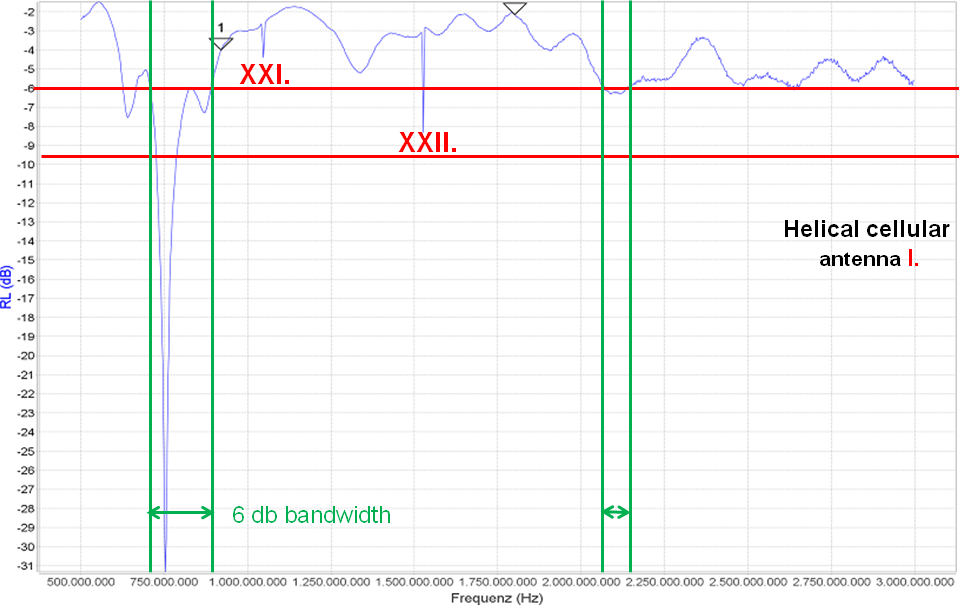
Return loss of cellular antenna I.
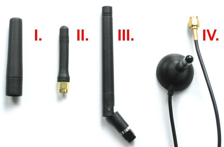
4 antennas tested with MiniVNA Tiny
The upper graph shows some interesting details. XXI and XXII are faults generated by the VNA. The peak close to 1100 MHz and 1500 MHz cannot be true. However, the peaks marked with XXI and XXII will be visible in the following graphs as well. Just ignore it and have a closer look on the two horizontal red lines which mark -6 dB and -9.5 dB return loss. The helical cellular antenna I does not have a chance to show a VSWR of 2, because the related -9.5 dB return loss shows a very small bandwidth (not marked) with green horizontal lines in sub GHz range and nothing at GSM 1800/1900 range. Even at -6dB return loss the resonant frequency is to low. Maybe the bandwidth at the lower band will fit. As mentioned before the ground plane of the VNA is for GSM 850/900 to small. Anyhow, at the higher GSM band the former mentioned bandwidth for GSM 1800 (74 MHz) or GSM 1900 (140 MHz) cannot be archived. This antenna is not a GSM dual band or GSM quad band antenna for sure.
The two triangles in the graph were in the exported origin PDF file. The markers were set inside the VNA software. The setting and changing the markers was not very logical. Please note that the two triangles mark the middle of the GSM 900 and GSM 1800 band. In the following reports you will find it again. During the test there was an export to Touchtone/SP1 file as well. These files for all four antennas you will find at download zone of the IoT M2M Cookbook. You can download it and make it visible with other software tools or load it to Atyune to generate a matching circuit by mouse click. To keep the Quick Start Guide simple, this effort will be saved for now and follow in further chapters. The target at this Quick Start Guide is to get several graphs for return loss on the screen within a view minutes.
The upper text is out of the IoT M2M Cookbook here. If you are interested in a copy of the book please do not hesitate to drop an email to harald.naumann (at) gsm-modem.de .
Remark: The low budget VNA had a to noisy output. The Smith Chart diagram contained to many loops and at UMTS 2100 and LTE 2700 the noise made the diagram close to unusable. I replaced it to a profesional VNA listed here.