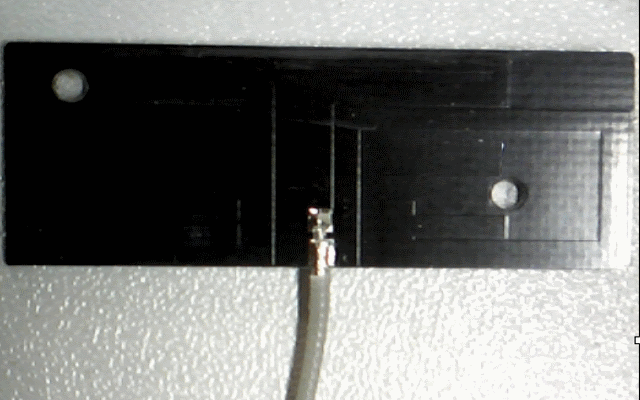
Penta band PCB antenna 40x15x0,4 mm
Our patient has a name. The manufacturers have called it the Penta-band PCB antenna. More details about the first mobile antenna patient are revealed in the test below.
Here are the medical records of the Penta-band PCB antenna:
- Frequency bands: GSM 850/900 MHz, GSM 1800 / 1900 MHz, UMTS 2100
- Frequency range: 824 – 960 MHz and 1710 – 2150 MHz
- VSWR @ 824 – 960 MHz max. 4 and VSWR @ 1710 – 2150 MHz max. 3
Return Loss max. in all bands: -9.5 dBm - Dimensions: 40 mm x 15 mm x 0.55 mm
- Cable: 1.13 mm diameter
- Cable length: 200 mm
- Connector type: U.FL
You can find this Penta Band PCB antenna online at different distributors. Some of them promise a VSWR of 3 in all frequency bands. The manufacturer told that the VSWR is measured on a test unit, but do not describe the test unit configuration. However, we re-tested the antenna in three different configurations.
Penta-band PCB antenna – test in three conditions
- Antenna in free space
- Antenna mounted on 0,4 mm FR4
- Antenna mounted on plastic enclosure (ABS)
Some initial details:
- VSWR: 2 = Return Loss of – 9.5 dBm
- VSWR: 3 = Return Loss of – 6 dBm
- VSWR: 4 = Return Loss of – 4.4 dBm
You can calculate this yourself here http://cgi.www.telestrian.co.uk/cgi-bin/www.telestrian.co.uk/vswr.pl
A VSWR of 3 is the common minimum for embedded antennas. However for some reason the manufacturer states a VSWR of 4 in the lower cellular bands.
Penta-band PCB antenna – free space
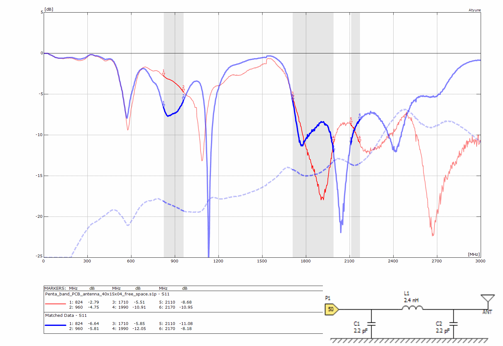
Penta band PCB antenna 40x15x0.4 mm
Red line not matched
- 824 MHz = RL -2.79 dBm / 1710 MHz = RL -5.51 dBm / 2110 MHz = – 8.68 dBm
- 960 MHz = RL -4.75 dBm / 1990 MHz = RL -10.91 dBm / 2190 MHz = – 10.95 dBm
Blue line matched with three components
- 824 MHz = RL -6.64 dBm / 1710 MHz = RL -5.85 dBm / 2110 MHz = – 11.08 dBm
- 960 MHz = RL -5.81 dBm / 1990 MHz = RL -12.05 dBm / 2190 MHz = – 8.18 dBm
A test in free space is not realistic. However, it is acceptable as a quick check. If the antenna does not show resonance in the promised bands or close to the promised bands then it makes no sense to use it in your IoT application. The red line shows the Return Loss without matching circuit and the blue line shows the Return Loss with a simulated matching circuit. In the right corner the graphic shows the schematic diagram with a PI circuit based on components from Murata (SMT 0402). After automatic simulation the capacitors had a value of 2.2 pF and 1.8 pF. I changed both to 2.2 pF and the result after manual simulation is still acceptable. Please click on the picture to enlarge it and to see more detail.
Penta-band PCB antenna – mounted on FR4
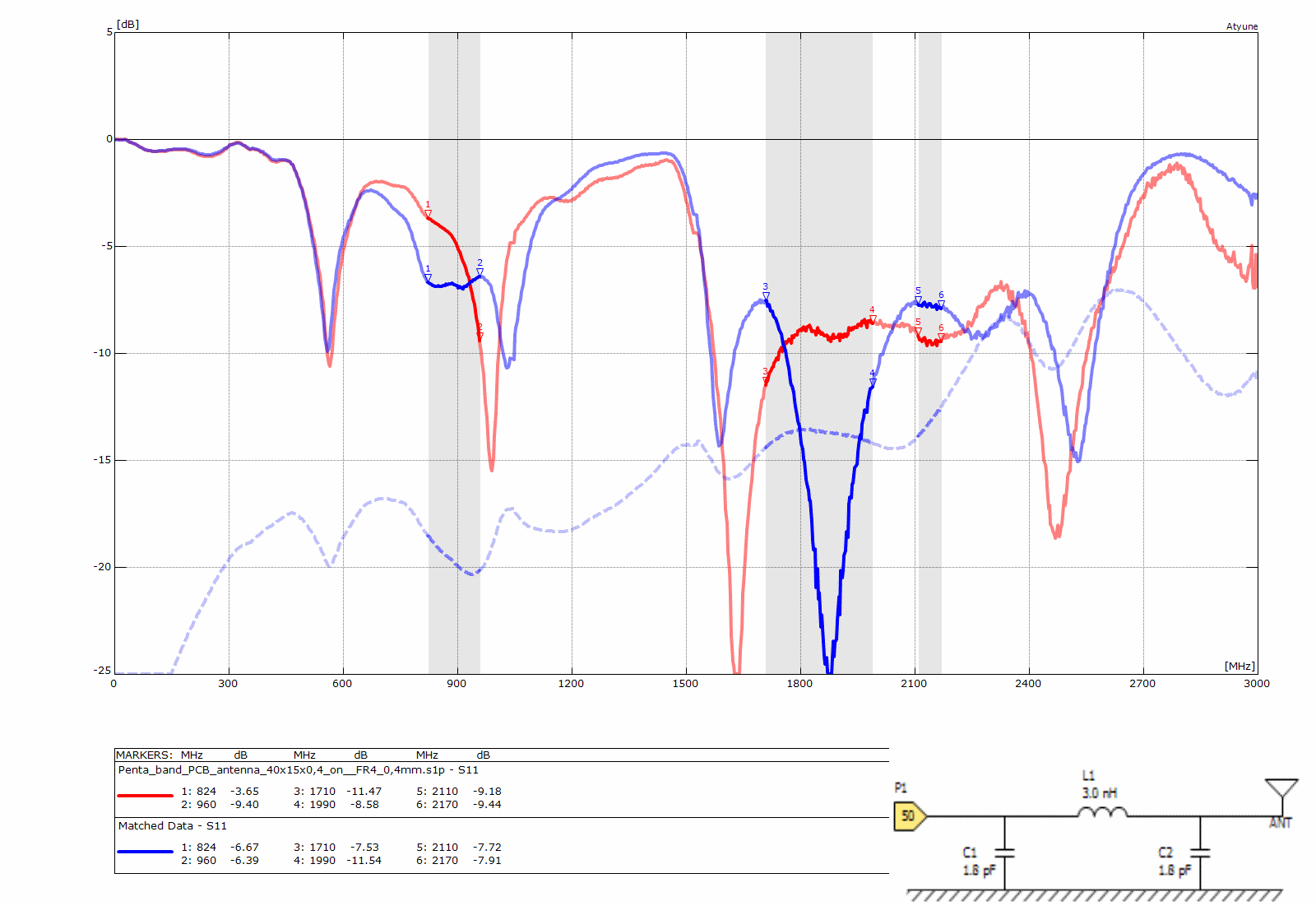
Penta band PCB antenna 40x15x0.4 mm
Red line not matched
- 824 MHz = RL -3.65 dBm / 1710 MHz = RL -11.47 dBm / 2110 MHz = -9.18 dBm
- 960 MHz = RL -9.40 dBm / 1990 MHz = RL -8.58 dBm / 2190 MHz = -9.44 dBm
Blue line matched with three components
- 824 MHz = RL -6.67 dBm / 1710 MHz = RL -7.53 dBm / 2110 MHz = -7.72 dBm
- 960 MHz = RL -6.39 dBm / 1990 MHz = RL -11.54 dBm / 2190 MHz = -7.91 dBm
The graph shows the antenna mounted on FR4 with thickness of 0.4 mm. If you compare it with the upper graph, then you can see that there is already a difference. The red line shows the Return Loss without matching circuit and the blue line shows the Return Loss with a simulated matching circuit. Without matching the Return Loss looks better. With matching circuit a Return Loss of – 6dBm can be achieved.
Penta-band PCB antenna – mounted on plastic
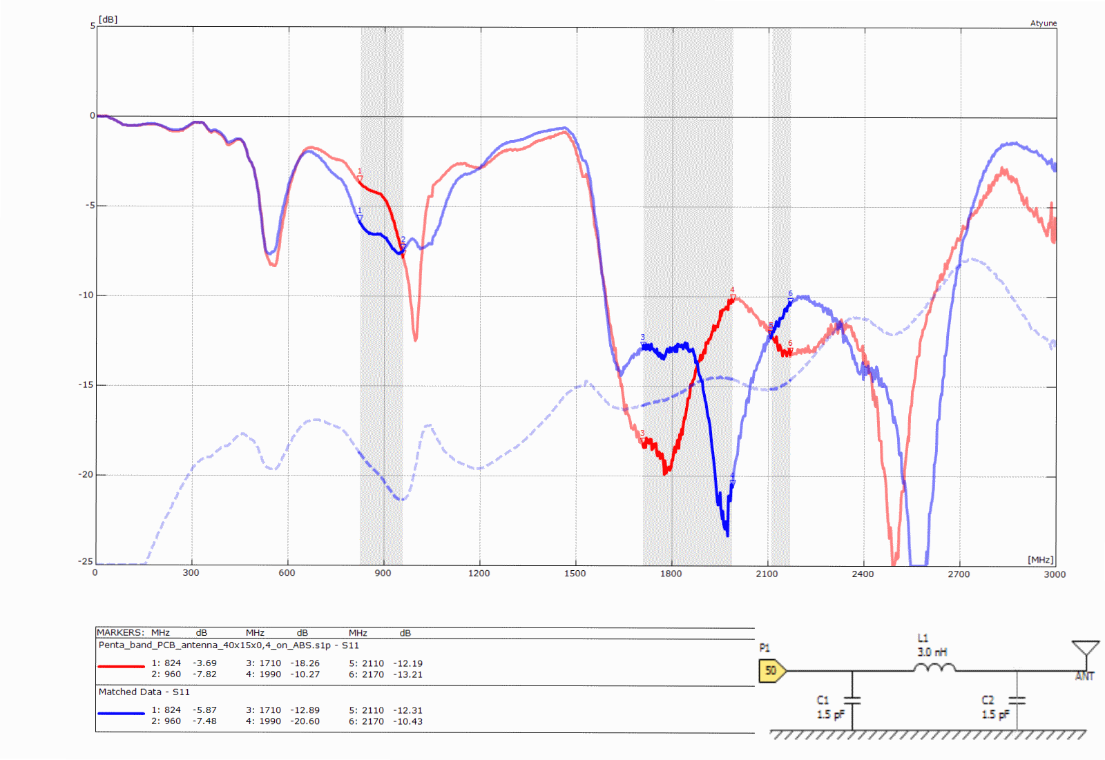
Penta band PCB antenna 40x15x0.4 mm
The graph shows the antenna mounted on ABS. If you compare it with the upper graph, then the claimed VSWR of 4 is almost achieved. We assume therefore that the unknown test unit was close to this test scenario. The red line shows the Return Loss without matching circuit and the blue line shows the Return Loss with a simulated matching circuit.
Penta-band PCB antenna – free space versus mounted on plastic
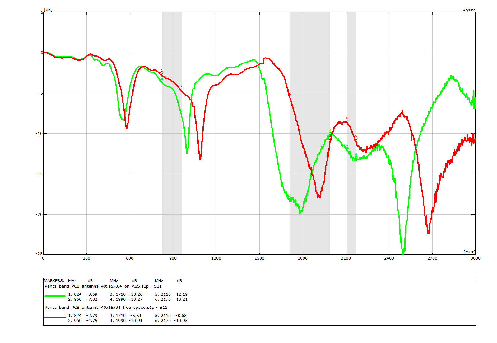
Penta band PCB antenna 40x15x0.4 mm
The red line shows the Return Loss in free space and the green line shows the Return Loss of the antenna mounted on plastic. If you have a closer look then you will note that the antenna is already optimised for mounting on some kind of plastic enclosure. The Return Loss in free space is out side the stated specification.
Some quick questions to consider:
-
Why do most of the antenna manufactures show PCB antennas tested in free space and why did this manufacturer go to the trouble of testing in a more realistic fashion, but then did not describe the test conditions?
-
And even if they had described how they tested – why didn’t they try to reach a VSWR of 6?
-
Why do they not discuss optimising performance by adding a impedance matching circuit?
Your Penta-band PCB antenna – mounted in your final enclosure
Your final solution will surely be different from these test conditions. If we test the same Penta-band PCB antenna in your special, customised environment again, then we will expect to get a different result. If your environment has a lot of metal close to the antenna, then the antenna that looks perfect based on its data sheet or tested in the above conditions may look poor in your special environment. Based on this fact, I came to the conclusion that an antenna test service would be a valuable offering. During my customer visits I am able to offer you a quick test, often free of charge. The Antenna Hospital launched in April 2015 in Milan and will migrate to an Antenna Ambulance. I will come with my mobile vector network analyser (VNA) to your office. During a cup of coffee I will measure the antennas in several configuration. This does not include just embedded PCB antennas; I offer the same service for external antennas.
The latest news is that the Antenna Hospital is now open for in-patient care. Anybody can send their antenna together with its enclosure to the Antenna Hospital in Germany.
If you have a patient for the Antenna Hospital or the Antenna Ambulance then do not hesitate to drop an email to harald.naumann (at) gsm-modem.de