The device under test is a PCB of size of 40 mm x 20 mm with GNSS antenna for a small tracking device. Small mobile GSM / GPS trackers are common for pets, humans or assets. Chip antennas operate as loop antennas which are magnetic antennas and are usually unaffected by being near to the body. If the PCB is touched or some objects come close to the antenna, the centre frequency of the antenna will not be de-tuned.
Operation of GPS chip loop antennas
Ceramic loop antenna with two visable pins
You can identify loop antennas by its two (three) connection pins. One pin will be connected the GPS module and the other will be connected to ground plane. They always have a cut-out zone without copper on all layers under the antenna. The pin to connect to the GPS module under the antenna like the pin at the picture below or 90 degree turned parallel to the other pin connected to ground. Such GPS antennas with its small bandwidth always need a tuning. With passive components between the GPS module and the antenna you can shift the centre frequency.
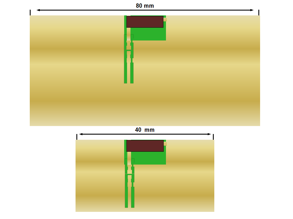
The upper graphic shows a GPS chip loop antenna on 80 mm and 40 mm long ground plane. Please note that the size of the GPS chip antenna is not to scale. The data sheets often specify the gain and Return Loss for 80 mm only. If you use a 40 mm long PCB instead of a 80 mm long PCB you will lose gain and bandwidth. If the bandwidth at 80 mm size is already at the edge then at 40 mm size it will be too small. If you move the antenna away from the centre of the 80 mm or 40 mm to the left or right side you will decrease gain as well.
GPS chip antenna bandwidth
According to the data sheet the selected antenna is suitable for GPS. The planned GNSS module is supporting GPS with a bandwidth of 1563 MHz to 1587 MHz and Glonass with a bandwidth from 1597 MHz to 1610 MHz. Since the two GNSS bands are so close together, you can specify it as a frequency band of 1587 MHz to 1610 MHz. The additional graphs show the same GPS antenna with a simulation of different matching circuits.
GPS chip antenna matched to GPS only
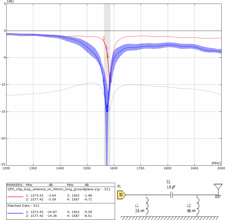
Ceramic loop antenna matched to GPS only
The red curve shows the GPS chip antenna unmatched on the PCB. The Return Loss peak at marker 4 shows -9.71 dB at 1597 MHz.
The blue curve shows the same GPS chip antenna matched by PI circuit to the GPS bandwidth (1563 MHz to 1587 MHz). The marker 3 and 4 are close to -10 dB. -10 dB is the common Return Loss at the GNSS band edges. The light blue curve shows the simulation with the tolerances of the components in the PI circuit. With tolerances the Return Loss is close to the -6 dB Return Loss bandwidth.
GPS chip antenna matched to GPS and Glonass version 1
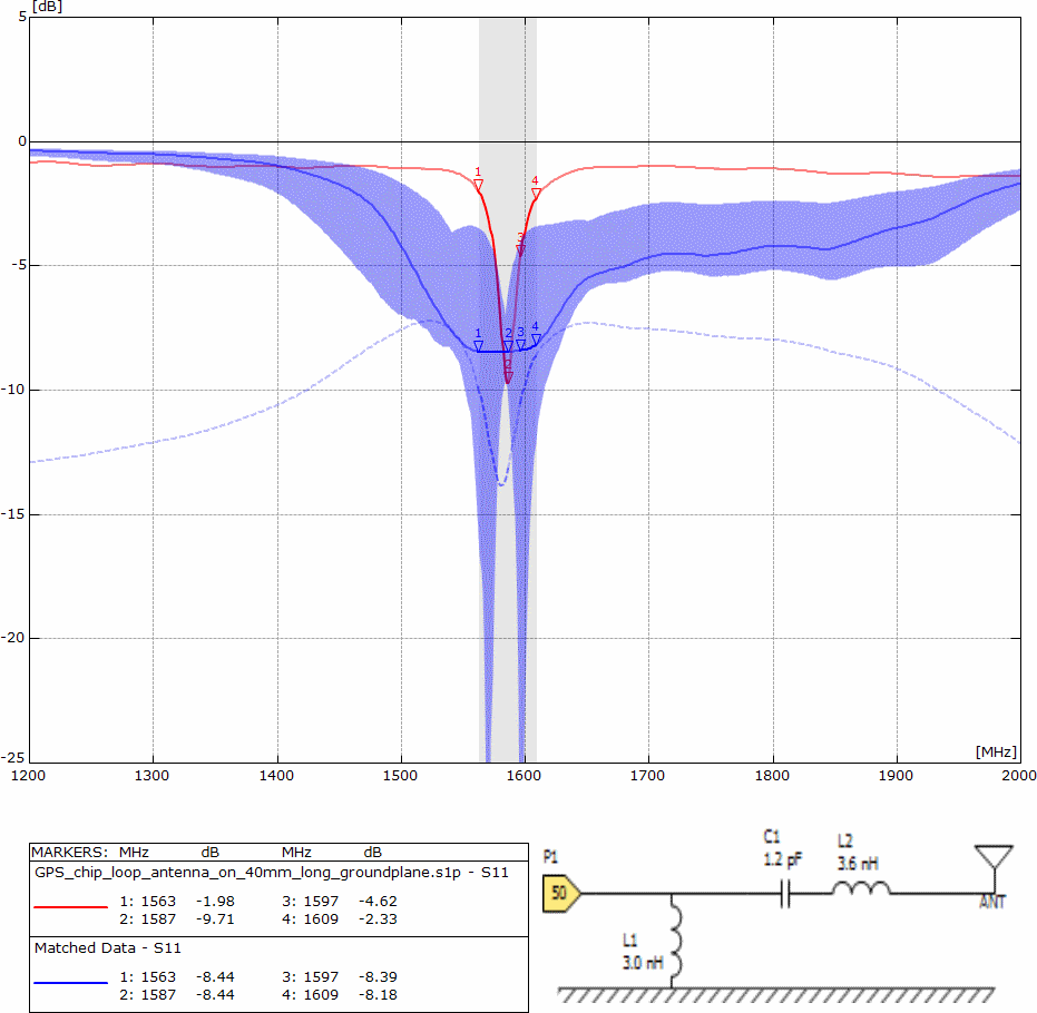
Ceramic loop antenna matched to GPS / Glonass – version 1
The blue matched shows the chip antenna matched with 3 parts in L circuit. The light blue curve of the simulation shows the tolerances of the components makes this matching proposal useless. Moreover, the antenna has a Return Loss of less than -4 dB at the GSM 1800 / 1900 MHz band. The transmitter of the GSM module will block the GPS module for sure. A smaller GNSS bandwidth will avoid this problem or at least reduce it.
GPS chip antenna matched to GPS and Glonass version 2
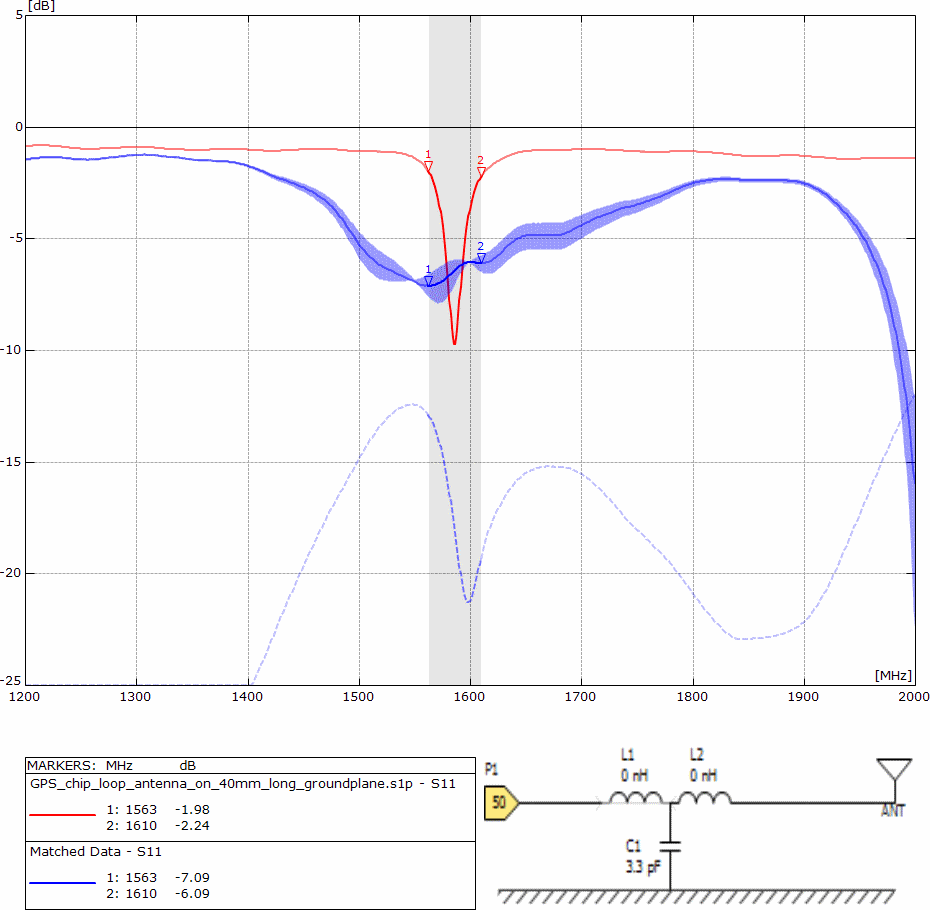
Ceramic loop chip antenna matched to GPS / Glonass – version 2
In this simulation the GPS band and Glonass band is already merged together from 1587 MHz to 1610 MHz. Even with the tolerances of the components the Return Loss is lower than -6 dB. The reason for the low tolerances is related to the capacitor of 3.3 pF to ground. If a matching circuit has fewer components the summary of all tolerances will be better as well. However, this plot shows a resonance at 2000 MHz and will may cause trouble at GSM 1900 and UMTS 2100.
GPS chip antenna matched by cut-out area
The red curve was already matched by changing the cut-out area under the GPS chip antenna. Matching of the GPS chip antenna by changing the cut-out area under the antenna is not listed in the data sheet. Such a tuning is too complex to explain for the standard IoT M2M developer. However, if the resonant frequency can be tuned by the cut-out area, this will avoid components in the matching circuit and lead to a much nicer tolerance curve for the Return Loss curve.
GPS chip antenna conclusion
The DUT has failed the test in several times. For GPS only the chip antenna is maybe okay, but other chip antennas will show a better result. For GPS plus Glonass, the antenna is not useful, because the Return Loss at the edges does not reach -10 dB. With tolerances the Return Loss will be worst case -4 dB at the edges only. Furthermore the Return Loss gets low at the cellular bands GSM 1800 and GSM 1900 as well. On GSM 1800 and GSM 1900 we have 1 Watt (30 dBm) power during transmit. The GNSS module will receive a high power peak and may be jammed.
For small devices like tiny trackers or Bluetooth wearables it is highly recommended to select and to test the chip antennas in beginning of the development including enclosure and battery. If the antenna will not pass this first test then you can stop your design to avoid misleading and faults during operation.
GPS chip antenna consulting
The DUT under tests has shown that there is a desperate need for antenna pre-tests. To avoid problems and faults there is a much better approach. The solution is an antenna pre-test by third party for just Euro 240 including documentation on Return Loss on a non-matched antenna, simulation of the matching circuit plus matching with passive components and measurement by Vector network analyser again.
- Test by VNA of the origin non matched antenna on PCB
- Export to S1P files and export to PNG files
- Simulation of the matching circuit
- Export to S1P files and export to PNG files again
- Test report in format PDF
The pre-test will always contain the test report and the S1P file of the origin PCB without matching. With the S1P file the customer of the pre-test can simulate matching circuits on its own again.
If you are interested in an antenna pre-test or antenna consulting for selection then do not hesitate to drop an email to harald.naumann (at) gsm – modem .de
Remark: Thanks to Michael Castle for his free proof reading
GPS antenna selection for a GSM / GPS tracker – DUT 1
GPS antenna selection for a GSM / GPS tracker – DUT 2
GPS antenna selection for a GSM / GPS tracker – DUT 3
GPS antenna selection for a GSM / GPS tracker – DUT 4