Do you use antennas in your products? Do you compare data sheets? Do you have problems comparing? Are the antennas in your device not compliant with the data sheet? Are there problems with radio certification? Then I will be glad to help you, starting with the analysis of the data sheets all the way up to the inexpensive test installation in the enclosure. Any enquiries should be addressed to harald.naumann (at) lte-modem.com.
In the following article I will analyse two dissimilar antenna data sheets. Since I am employed with a special distributor for wireless modules and antennas, I have access to a bunch of antennas from various manufacturers. As an independent author of the IoT M2M Cookbook, I’m extremely busy with antennas. In the meantime I own a Vector Network Analyser and an Antenna Radiation Pattern Test System. From time to time I develop an antenna myself. Writing books, cooking, painting or developing antennas is simply an expression of creativity.
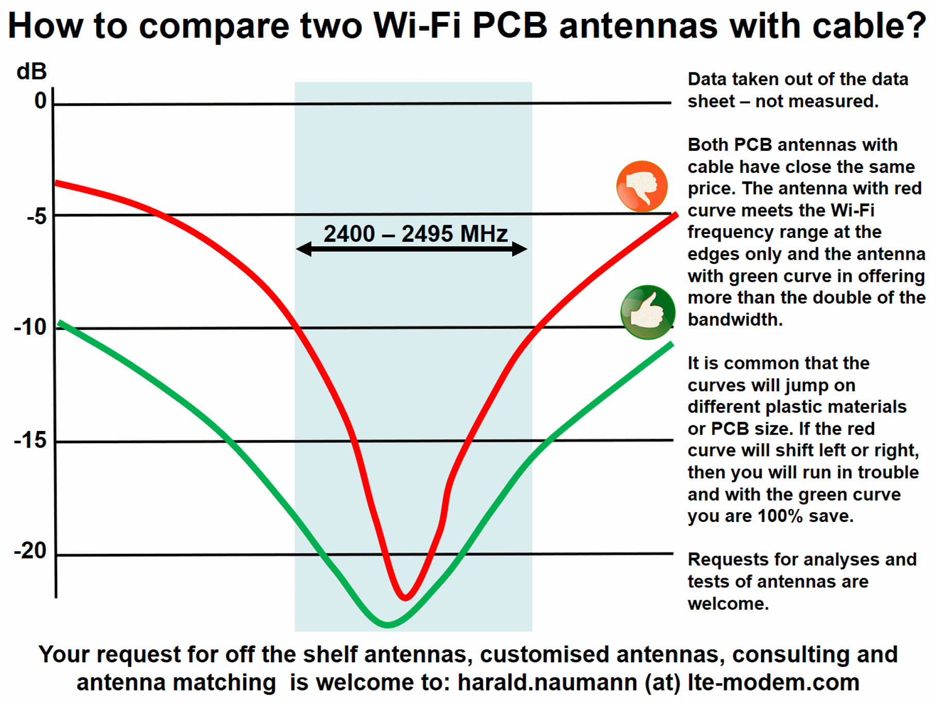
A client wanted an offer for Wi-Fi/BLE antennas on FR4 or Flex-PCB with 100 mm cable and U.FL plug. We have designed such antennas several times in our program. I chose two with similar prices and compared the data sheets, however the graphs of return loss were on different scales. In order to make a comparison I electronically cut out the two return loss graphs and layered them in PowerPoint. Afterwards I changed the size of the graphics and to match the scales. In the next step I redrew the two curves and in the last step I deleted the two graphics and inserted the dimensioning in the axes.
Wow, 3.2 dBi gain and 79 % antenna effiency (red)
At first glance the first Wi-Fi PCB antenna (red) looks better than the second selected antenna (green). The first antenna shows us 3.2 dBi antenna gain at its peak in the data sheet. Furthermore, the data sheet of the first antenna states an antenna efficiency of 79 %. However, this 79 % was only measured and named at one measuring point in the peak.
Just 3.0 dBi gain and only 60% antenna effiency (green)
For the second antenna, we find 3.0 dB antenna gain at the peak in the data sheet. Furthermore, the data sheet mentions an antenna efficiency of >60 %. The antenna efficiency was measured in three axes and then the mean value was calculated. In addition, the second antenna shows the directional diagram of the antenna in the three axes.
Wi-Fi BLE Bluetooth PCB antenna with cable
Return loss compared
The return loss of the two antennas was difficult to compare. Hence the collage described above. With the first antenna, the return loss or the bandwidth of the antenna at -10 dB return loss was highlighted. For the second antenna, the return loss of the antenna on the Wi-Fi band corners was given as -19 dB at the lower end of the band and -15 dB at the upper end of the band. Since the scale of the data sheet of the second antenna is much larger and more accurate, it can be seen that the -10 dB bandwidth of the second antenna is much better than that of the first antenna. The second antenna is also has double resonance at 2400 and 5000 MHz. Despite the double resonant frequency, the antenna offers a wider bandwidth than the first antenna.
Antenna performance and price
The prices are similar and the difference in antenna performance is big. The two data sheets support what we already mentioned in our recent LPWAN seminar. Many manufacturers name their antenna parameters only at the top. The antenna efficiency of a unidirectional antenna is always measured and indicated in all directions. It is even the other way round. An antenna of a certain, known arrangement can physically or mathematically only achieve a known average efficiency. In this case it is a typical monopole antenna. If the efficiency in the peak is much higher than with the typical ideal antenna, then this indicates a directional effect. This is best seen with directional antennas (e.g. Yagi antenna). The antenna gain of a directional antenna is always much higher than that of an omnidirectional monopole antenna. With handheld devices or sensors, an omnidirectional characteristic is generally preferred.
Conclusion of the antenna comparison
The antenna with only 60 % antenna effiency is the much better antenna.
Recommenation for antenna designs:
As already mentioned in the seminars, the measuring instruments for antenna measurements for return loss and for antenna radiation patterns are available. Requests for measurements are welcome.
How the two antennas in your housing behave with your PCB is another topic. We always recommend a sample setup with antenna and empty board in the original housing or a similar housing.
Thank you in advance for your request for antenna samples, measurements or test setups to harald.naumann (at) lte-modem.com
HI , i’ve found out through Simulations , that any metal over Styrofoam antenna could leave in the dust any PCB antenna of similar size for Efficiency (FR4 , etc) not so bad on Teflon , Rogers or Neltec under 1mm thickness though
Hi Claude,
I found the same by developing such metal bent antennas. However, the metal bent antenna you can not glue to the plastic enclosure.
Regards
Harald